
User manual


Toolbox 32 User Manual 1.47d www.cse-semaphore.com/mykingfisher
Page
69
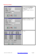
Ladder Logic - Outputs
The right-most column of ladder logic is used for Ladder Output blocks. These blocks cause something to
happen - like a register bit to be set, a message to be transmitted or a calculation to be performed. Ladder
Output blocks are processed when connected to a ladder rung that is logically true. The various types of
ladder outputs are detailed in the following sections.
Output blocks include: Coil, Copy, Maths, Logic, Event Logging, Tx/Rx Comms, Pager Message, Function
and Program Blocks, P.I.D., AGA-8, AGA-9, Clock Synchronization, Report Printer and Image Monitoring
Functions.
Ladder Logic - Coil
A coil parameter can be any read/write bit. These include local register bits (eg. #R1.1), hardware register
bits (eg. #DO3.16), internal register bits (eg. #YDIAG.1) and network bits (eg. #NR5.1.1, #ND2.14.9).
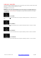
Normal Coil
When the input condition is true, the parameter is turned ON. When the input condition is false, the
parameter is turned OFF. Eg. bit 1 of R1 is turned ON when the rung is true and is turned OFF when the
rung is false. As used in the topic Example - Timer Flag.
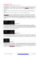
Negated Coil
When the input condition is true, the parameter is turned OFF. When the input condition is false, the
parameter is turned ON. Eg. bit 1 of R1 is turned OFF when the rung is true and is turned ON when the rung
is false.
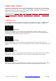
Set Coil
When the input condition is true, the parameter is turned ON. No action is taken when the input condition is
false. Eg. bit 1 of R1 is turned ON when the rung is true and is unchanged when the rung is false.
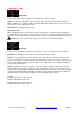
Reset Coil
When the input condition is true, the parameter is turned OFF. No action is taken when the input condition is
false. Eg. bit 1 of R1 is turned OFF when the rung is true and is unchanged when the rung is false.