
User manual


Toolbox 32 User Manual 1.47d www.cse-semaphore.com/mykingfisher
Page
91
Ladder Logic - P.I.D. Block
The PID block is used to monitor a process variable (eg. flowrate) and compare it to a setpoint (eg. desired
flowrate). According to the difference between the actual value and the setpoint value, the PID block sets a
Control Variable (eg. valve position) to reduce the error. The control variable is gradually changed until the
desired setpoint is achieved within the deadband limits.
The rate of change of the Control Variable is configurable so that for delicate processes, the output rate of
change can be small and for robust processes requiring quick responses, the output rate of change can be
high.
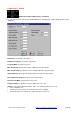
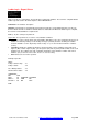
The example shown below is used to control a valve to achieve a setpoint flowrate. The output of the PID is
stored in #R1 (which is used to control the valve position). The actual valve position is read from #AI14.2,
and the required flowrate is stored in #R2. The PID block uses reverse action and a proportional gain of 1 so
that a drop of say 5% in flowrate (#AI14.2) will result in an increase of 5% in valve position (#R1). In addition
an Integral Factor of 0.1 units/min is used so that the valve position will be increased at a rate of 0.5% each
minute until the flowrate is within 1% (327) of the setpoint. As the PID block is in Auto mode, the Raise and
Lower parameters are not used.
Figure: Example PID Advanced Block.
Note: the standard PID block does not have the Anti Reset Band parameters.
Comment: A 12-character description.
Block Number (1-16): The PID block number in the ladder. Up to 16 PID blocks can be configured in ladder
logic.
Control Variable: (16-bit register) The output of the PID block used to control a process to produce the
desired Set Point. This can be a hardware register or a local register.
Process Variable: (16-bit register) The input that is monitored by the PID block. Process error is determined
from the difference between the Process Variable and the Set Point. The process variable is usually an
analog input which is stored in the RTU as a number in the range 0-32760 (equivalent to 0.00 - 100.00%).