
Installation manual

14
11921 Slauson Ave. Santa Fe Springs, CA. 90670 (800) 227-4116 FAX (888) 771-7713
WELDING LIFTGATE TO VEHICLE - Continued
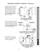
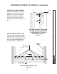
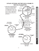
Steel mounting channels shall be
10 gauge material, 8” in length
(FIG. 14-1). All other dimensions
shall suit dimensions of vehicle
corner posts. Drill 10 holes to
larger side of mounting channel,
and 5 to smaller face. Drillings
should be suitable to accept 1/4”
drive rivets. FIG. 14-1 shows
locations for drillings.
DRILLINGS LOCATIONS ON
STEEL MOUNTING CHANNELS
FIG. 14-1
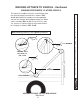
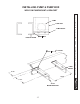
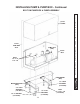
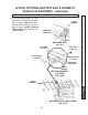
Position and rivet each steel mount-
ing channel using 1/4” drive rivets
as shown in FIG. 14-2. The 10 drill-
ing face is located over outside face
of corner post (FIG. 14-2). Position
for upper and lower mounting chan-
nels is shown in FIG. 13-1.
POSITION AND RIVET STEEL MOUNTING
CHANNELS TO VEHICLE CORNER POST
FIG. 14-2
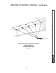
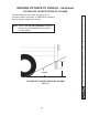
After installing the 4 mounting
channels, hoist unit into position
and weld to mounting channels
as shown in FIG. 14-3.
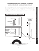
WELDING COLUMN ASSEMBLY TO
STEEL MOUNTING CHANNEL
(LH COLUMN IS SHOWN)
FIG. 14-3
2” LONG
1/4”
OUTSIDE OF
COLUMN
INSIDE OF
COLUMN
OUTSIDE FACE
IF CORNER
POST
(LH POST IS
SHOWN)
STEEL
MOUNTING
CHANNEL
(4 PLACES)
FRONT FACE OF
CORNER POST
1-3/4”
1-3/4”
1-3/4”
1-3/4”
1/2”
1/2”
1/2”
1-3/4”
1-3/4”
1-3/4”
1-3/4”
1/2”
1/2”
1/2”