OPERATING INSTRUCTIONS FOR WHEELCHAIR LIFT MODEL NO. • WL7-vers. C • WL7-vers. C-1K DOT-Public Use Lift ‘‘DOT-Public Use Lift’’ verifies that this platform lift meets the ‘‘public use lift’’ requirements of FMVSS No. 403. This lift may be installed on all vehicles appropriate for the size and weight of the lift, but must be installed on buses, school buses, and multipurpose passenger vehicles other than motor homes with a gross vehicle weight rating (GVWR) that exceeds 4,536 kg (10,000 lb).
PATENTS PENDING
TABLE OF CONTENTS INTRODUCTION ............................................................................................... 4 SAFETY SUMMARY ......................................................................................... 4 DAILY PRE-OPERATION & OPERATION CHECKLIST .................................. 6 MAINTENANCE SCHEDULE ........................................................................... 8 LIFT COMPONENTS & TERMINOLOGY........................................................
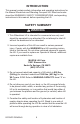
INTRODUCTION This manual contains safety information and operating instructions for the Maxon Wheelchair and Standing Occupant Lift. Read and understand the WARNINGS, SAFETY CONSIDERATIONS, and operating instructions in this manual, before operating the Lift. SAFETY SUMMARY ! WARNING 1. This Wheelchair Lift is intended for commercial use only and should be operated by an attendant. Do not attempt to ride Lift without the assistance of an attendant. 2.
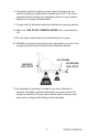
6. If possible, park the vehicle on level ground. Always set the vehicle emergency brake before operating the Lift. If the Lift is operated without setting the emergency brake, it may create a hazard for occupant and attendant. 7. Comply with all attached instruction decals and warning decals. 8. Above all, USE GOOD COMMON SENSE when operating this Lift. 9. Do not move vehicle when the wheelchair door is open. 10.
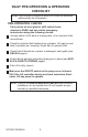
DAILY PRE-OPERATION & OPERATION CHECKLIST NOTE: PRE-OPERATION and OPERATION CHECKS should be performed by the Lift operator. PRE-OPERATION CHECKS Park vehicle on level ground, shift vehicle transmission to PARK, and set vehicle emergency brake before doing the following checks. Visually check Lift for bent or broken parts, or for hydraulic fluid around base. Check for hydraulic fluid leaking from cylinders. Lift may be operated if cylinders are “weeping” a light film of hydraulic fluid.
OPERATION CHECKS Operate the Lift through one full cycle and do the following checks. Use Lift operating instructions in this manual to UNFOLD, LOWER, RAISE, and FOLD platform. Make sure the Lift responds properly to switches on the hand pendant. Listen for unusual noises while the Lift operates. Watch for uneven movement of the Lift arms, platform, and inboard and outboard rollstops.
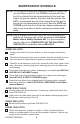
MAINTENANCE SCHEDULE NOTE: The Lift controller (brain box) counts the number of cycles & lifts over the lifetime of the Lift. One CYCLE is counted each time the Lift is unfolded from the stowed position to floor level, lowered to the ground, raised to floor level, and then stowed. One LIFT is counted each time the Lift is lowered from floor level to the ground, and raised back to floor level.
THIS PAGE INTENTIONALLY LEFT BLANK 9 PATENTS PENDING
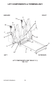
LIFT COMPONENTS & TERMINOLOGY INBOARD RIGHT 10 6 4 11 10 6 7 8 12 5 2 9 1 12 3 LEFT OUTBOARD LIFT COMPONENTS (SEE TABLE 11-1) FIG.
ITEM NAME DESCRIPTION 1. THRESHOLD PLATE Component that bridges the entry way, through the Lift, into the vehicle. Detects if that portion of Lift is occupied during “UP/ DOWN” operation between vehicle floor and the ground. 2. OUTBOARD ROLLSTOP Barrier to prevent the wheelchair from rolling off of the platform. Also provides entry/exit ramp for platform on the ground. 3. PLATFORM Contains the wheelchair and occupant during “UP/DOWN” operation between vehicle floor and the ground. 4.
DECALS AND DECAL PLACEMENT DECAL ”D” DECAL “O” DECAL “K” DECAL “A” DECAL “B” DECAL “F” DECAL “L” DECAL “M” DECAL“J” DECAL “I” DECAL“N” DECAL “C” DECAL “E” DECAL“N” DECAL “H” FIG. 12-1 All WARNING, CAUTION, and OPERATION decals provided with Wheelchair Lift must always be in place on the Lift and must always be legible. If decals are missing or illegible, get free replacement decals from: MAXON Lift Corp. - Customer Service 11921 Slauson Ave.
DECALS FOR WL7-vers. C DECAL SET P/N 268302-01 FIG.
DECALS AND DECAL PLACEMENT- Continued DECALS FOR WL7-vers. C-1K DECAL SET P/N 268302-03 FIG.
SERIAL PLATE & CONTROLLER OVERLAY CONTROLLER OVERLAY P/N 2667630-01 FIG. 15-1 SERIAL PLATE P/N 905246-8 FIG.
ANTI-SLIP & SAFETY STRIPING (30” WIDE PLATFORM) YELLOW TAPE (BOTTOM-ROLLSTOP) P/N 905293-17 ANTI-SLIP TAPE (ROLLSTOP) P/N 096020-13 ANTI-SLIP TAPE P/N 096020-10 ANTI-SLIP TAPE P/N 096024-10 ANTI-SLIP TAPE P/N 096013-10 YELLOW TAPE (OUTBOARD) P/N 905293-11 YELLOW TAPE (OUTBOARD) P/N 905293-14 YELLOW TAPE (INBOARD) P/N 905293-16 ANTI-SLIP TAPE (ROLLSTOP) P/N 096020-13 YELLOW TAPE P/N 905293-11 YELLOW TAPE P/N 905293-14 FIG.
(33” WIDE PLATFORM) YELLOW TAPE (BOTTOM-ROLLSTOP) P/N 905293-18 ANTI-SLIP TAPE (ROLLSTOP) P/N 096020-14 ANTI-SLIP TAPE P/N 096020-11 ANTI-SLIP TAPE P/N 096024-11 ANTI-SLIP TAPE P/N 096013-11 YELLOW TAPE (OUTBOARD) P/N 905293-11 YELLOW TAPE (OUTBOARD) P/N 905293-14 YELLOW TAPE (INBOARD) P/N 905293-16 ANTI-SLIP TAPE (ROLLSTOP) P/N 096020-14 YELLOW TAPE P/N 905293-11 YELLOW TAPE P/N 905293-14 YELLOW TAPE (INBOARD & OUTBOARD) P/N 905293-15 FIG.
ANTI-SLIP & SAFETY STRIPING - Continued (34” WIDE PLATFORM) YELLOW TAPE (BOTTOM-ROLLSTOP) P/N 905293-18 ANTI-SLIP TAPE (ROLLSTOP) P/N 096020-15 ANTI-SLIP TAPE P/N 096020-12 ANTI-SLIP TAPE P/N 096024-12 ANTI-SLIP TAPE P/N 096013-11 YELLOW TAPE (OUTBOARD) P/N 905293-11 YELLOW TAPE (OUTBOARD) P/N 905293-14 YELLOW TAPE (INBOARD) P/N 905293-16 ANTI-SLIP TAPE (ROLLSTOP) P/N 096020-15 YELLOW TAPE P/N 905293-11 YELLOW TAPE P/N 905293-14 FIG.
THIS PAGE INTENTIONALLY LEFT BLANK 19 PATENTS PENDING
OPERATING INSTRUCTIONS ENTER VEHICLE NOTE: If equipped, seat belt must be fastened for Lift to operate. 1. Fully open and secure Wheelchair Lift access door(s) on the vehicle. ON OFF PUMP COVER POWER SWITCH (LH PUMP SHOWN) FIG. 20-1 2. Apply power to the Lift by turning on the switch on the pump cover (FIG. 20-1). The POWER light on the hand pendant illuminates (FIG. 20-2). DOWN UNFOLD POWER (ON) LIGHT HAND PENDANT FIG. 20-2 3. Push the UNFOLD switch on hand pendant (FIG.
4. Push the DOWN switch on hand pendant (FIG. 18-2) to lower platform to ground level (FIG. 21-1). LOWER PLATFORM TO GROUND FIG. 21-1 5. If equipped, unfasten seat belt (FIG. 21-2). Place on hanger (FIG. 21-3). UNFASTENING SEAT BELT (RH HANDRAIL SHOWN) FIG. 21-2 SEAT BELT ON HANGER (LH HANDRAIL SHOWN) FIG. 21-3 6. Position wheelchair or ambulatory occupant on the center of platform (FIG. 21-4). Set wheelchair brakes or switch off powered wheelchair. POSITIONING OCCUPANT ON PLATFORM AT GROUND LEVEL FIG.
OPERATING INSTRUCTIONS - Continued 7. If equipped, fasten seat belt (FIG. 22-1). FASTENING SEAT BELT (RH HANDRAIL SHOWN) FIG. 22-1 8. Push the UP switch on hand pendant (FIG. 22-2) to raise platform to vehicle floor level (FIG. 22-3). UP DOWN UNFOLD HAND PENDANT FIG. 22-2 RAISING LIFT UP TO VEHICLE FLOOR LEVEL FIG. 22-3 9. Release wheelchair brakes or switch on powered wheelchair. Move wheelchair or ambulatory occupant inside the vehicle.
EXIT VEHICLE 1. Fully open and secure Wheelchair Lift access door(s) on the vehicle. FLOOR LEVEL PLATFORM LIGHT 2. Push the UNFOLD switch on hand pendant (FIG. 22-2) to unfold platform to horizontal position (FIG. 23-1) until platform lights come on. UNFOLD PLATFORM FIG. 23-1 3. If equipped, make sure seat belt is fastened (FIG. 23-2). FASTENING SEAT BELT (RH HANDRAIL SHOWN) FIG. 23-2 4. Position wheelchair or ambulatory occupant on the center of platform (FIG. 23-3).
OPERATING INSTRUCTIONS - Continued 6. If equipped, unfasten seat belt (FIG. 24-1). Place on hanger (FIG. 24-2). UNFASTENING SEAT BELT (RH HANDRAIL SHOWN) FIG. 24-1 SEAT BELT ON HANGER (LH HANDRAIL SHOWN) FIG. 24-2 7. Release wheelchair brakes or switch on powered wheelchair. Move wheelchair or ambulatory occupant into the passenger unloading zone.
STOW LIFT 1. If equipped, fasten seat belt (FIG. 25-1). FASTENING SEAT BELT (RH HANDRAIL SHOWN) FIG. 25-1 UP 2. Push the UP switch on hand pendant (FIG. 25-2) to raise platform to vehicle floor level (FIG. 25-3). FOLD HAND PENDANT FIG. 25-2 RAISING LIFT TO VEHICLE FLOOR LEVEL FIG. 25-3 3. Push the FOLD switch on hand pendant (FIG. 25-2) to fold platform (FIG. 25-4). Fold operation will stop automatically when completed. FOLDING PLATFORM UP INTO VEHICLE FIG.
MANUAL PUMP OPERATION LOADING & UNLOADING OCCUPANT LATCH 1. Reposition latches to manually unfold the Lift as follows. Raise latch off anchor pin (FIG. 261A) on LH side of Lift. Position the standoff to REPOSITIONED hold latch in place above LATCH & STANDOFF the anchor pin (FIG. FIG. 26-1B 26-1B). Repeat for latch on RH side of Lift. STANDOFF ANCHOR PIN LIFT - BACK VIEW FIG. 26-1A 2. Remove the manual backup handle from clips on the pump cover (FIG. 26-2).
3. Unfold the platform as follows. Open release valve on manual pump by turning manual backup handle counter-clockwise (FIG. 27-1). Start with 1/4 turn and slowly increase to 1/2 turn counterclockwise. 1/4 - 1/2 TURN OPEN RELEASE VALVE FIG. 27-1 4. Observe the platform unfolding to horizontal position at vehicle floor level (FIG. 27-2). UNFOLD PLATFORM FIG. 27-2 5. When the platform reaches floor level, close release valve on manual pump by turning manual backup handle clockwise until tight (FIG.
MANUAL PUMP OPERATION - Continued OUTBOARD ROLLSTOP 6. Ensure outboard rollstop is raised all the way (FIG. 28-1). OUTBOARD ROLLSTOP RAISED UP FIG. 28-1 7. If equipped, make sure seat belt is fastened (FIG. 28-2). FASTENING SEAT BELT (RH HANDRAIL SHOWN) FIG. 28-2 NOTE: If there are no occupants to unload from vehicle, skip step 8. 8. Position wheelchair or ambulatory occupant on the center of platform (FIG. 28-3). Set wheelchair brakes or switch off powered wheelchair.
9. Lower the platform as follows. Re-enter the vehicle to access manual pump. Open release valve on manual pump by turning manual backup handle counter-clockwise (FIG. 291). Lower the Lift slowly below floor level and check if inboard rollstop is raised and locked in the up position (FIG. 29-2). OPEN RELEASE VALVE FIG. 29-1 INBOARD ROLLSTOP PLATFORM LOWERED, INBOARD ROLLSTOP UP FIG. 29-2 10. Watch platform (FIG. 293) as it lowers occupant to the ground. LOWERING PLATFORM TO GROUND FIG. 29-3 11.
MANUAL PUMP OPERATION - Continued 12. If equipped, unfasten seat belt (FIG. 30-1). Place on hanger (FIG. 30-2). UNFASTENING SEAT BELT (RH HANDRAIL SHOWN) FIG. 30-1 SEAT BELT ON HANGER (LH HANDRAIL SHOWN) FIG. 30-2 13. Ensure outboard rollstop on the platform is opened to the horizontal position (FIG. 30-3). OUTBOARD ROLLSTOP NOTE: If there are no occupants to unload, skip steps 14 & 15. OUTBOARD ROLLSTOP IN HORIZONTAL POSITION FIG. 30-3 14. Release wheelchair brakes or switch on powered wheelchair.
CAUTION Prevent the manual backup handle from getting damaged. Before you start pumping with the handle, line up notches on tip of handle as shown in FIG. 29-1. Then fully engage handle with manual pump as shown in FIG. 29-2. NOTCHES LINED UP VERTICAL HANDLE - NOTCHES LINED UP CORRECTLY FIG. 31-1 HANDLE FULLY ENGAGED FIG. 31-2 17. Raise the platform as follows. Insert manual backup handle in manual pump actuator. Pump the handle up and down (FIG.
NOTE: If there are no occupants to load on platform, skip step 18. 18. Release wheelchair brakes or switch on powered wheelchair. Move wheelchair or ambulatory occupant inside the vehicle. PUMPING MANUAL BACKUP HANDLE FIG. 32-1 19. Stow the Lift as follows. Pump the manual backup handle up and down (FIG. 32-1) until platform folds up tightly inside the vehicle (FIG. 32-2). FOLDING PLATFORM UP INTO VEHICLE FIG. 32-2 20. Store manual backup cover on pump cover (FIG. 32-3) using the clips provided.