
Owner manual


Gamatronic Electronic Industries Ltd.
POWER
+
RM
50 KVA, N.Am. Std. – User Guide, Release 1.9
146
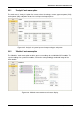
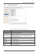
8.15.9.3 Third General Screen
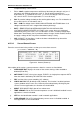
From the screen shown in the previous section, press ► to view screen 3:
[3-second Esc > GENERAL > ► > ►]
BOARD JUMPERS SETTING:
1. Not HARD Silicon
2. Silicon Mode 6. No Rmt Pan.
3. CAPACITY HI 9. AC: 120V
Figure 301: General (Screen 3)
A description of the various system parameters shown in screen 3 are listed below:
a. Not HARD Silicon: Must be HARD only initially, during first activation of non-configured
controller. After production, it should be Not HARD Silicon.
b. Silicon Mode: Regular mode allowing setup change. The setups are saved in an
EEPROM chip.
c. CAPACITY HI (LO): High/low battery capacity mode when battery capacity is more/less
than 100 Ah to achieve optimal resolution of the displayed value of battery current.
d. No/Yes Rmt Pan: Outputs of system controller are not configured or configured for an
optional remote panel connection.
e. AC: 220 V: Nominal ac input voltage: 220 V for 2x32 batteries, 110 V for 2x16 batteries
in series.
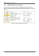
8.15.9.4 Fourth General Screen
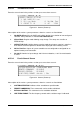
From the screen shown in the previous section, press ► to view screen 4.
[3-second Esc > GENERAL > ► > ► > ►]
SYSTEM OPERATION: STANDALONE MODE
REMOTE COMMANDS: DISABLE
BYPASS CONTROL: DISABLE
LINE FREQ./RANGE: AutoHz / 2Hz
Figure 302: General (Screen 4)
A description of the various system parameters shown in screen 4 are listed below.
a. SYSTEM OPERATION: Indicates either standalone or parallel mode.
b. REMOTE COMMANDS: These commands can be enable or disabled.
c. BYPASS CONTROL: This command can be enabled or disabled.
d. LINE FREQ./RANGE: The line frequency control and its variation range is indicated.