
Owner manual


Gamatronic Electronic Industries Ltd.
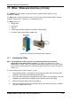
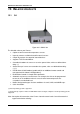
POWER
+
RM
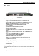
50 KVA, N.Am. Std. – User Guide, Release 1.9
171
13. OPERATING THE MAINTENANCE BYPASS SWITCH
In maintenance bypass mode, the UPS output terminals continue to supply power to the load, but
the interior of the UPS is isolated from all power flows. This enables a technician to work safely
on the UPS (after turning off the battery circuit breaker) without any interruption of power to the
load.
13.1 Putting the UPS in maintenance bypass mode
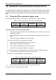
In normal operation, the UPS's ac circuit breakers are positioned as shown in Table 24.
Table 24: Normal operating position of the ac circuit breakers
RECTIFIER
AC INPUT
BYPASS
AC INPUT
AC OUTPUT
MAINTENANCE
BYPASS
ON ON ON OFF
To put the system in maintenance bypass mode:
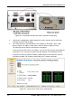
1. Verify that the bypass indicator is lit on the Static Switch. (If it is not lit, the UPS cannot
go into bypass mode.)
2. On the Controller front panel, press the INV/BYP button twice to put the UPS in bypass
mode.
3. Verify that the bypass indicator is lit on the controller.
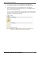
Then, operate the UPS's ac circuit breakers as follows:
4. Switch ON the MAINTENANCE BYPASS circuit breaker.
5. Switch OFF the AC OUTPUT circuit breaker.
6. Switch OFF the RECTIFIER AC INPUT circuit breaker.
7. Switch OFF the BYPASS AC INPTU circuit breaker.
The ac circuit breakers are now positioned as ac OUTPUT switch (the right-side switch).
8. Switch OFF the rectifier INPUT switch (the left-side switch).
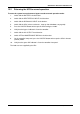
The switches are now positioned as shown in Table 25.
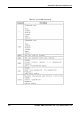
Table 25: Position of the ac CBs in maint. bypass mode
RECTIFIER
AC INPUT
BYPASS
AC INPUT
AC OUTPUT
MAINTENANCE
BYPASS
OFF OFF OFF ON
9. Switch OFF the BATTERY circuit breaker on the UPS rear panel.
The system is now in maintenance bypass mode.