Exceeding Your Wireless Expectations 24XStream™ Wireless OEM Module Operating Manual v2.8 MaxStream, Inc. 1215 S. 1680 W. Orem, UT 84058 Phone : (801) 765-9885 Fax: (801) 765-9895 info@maxstream.net http://www.maxstream.
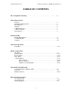
©2001 MaxStream, Inc. 24XStream™ Wireless OEM Module Manual v2.8 TABLE OF CONTENTS FCC Compliance Warning……………………………………………………… 4 General Description Features…………………………………………………………………………… 5 Simple Product Integration……………………………………………………….. 5 Block Diagram……………………………………………………………………. 6 Diagram…………………………………………………………………………… 6 J1 Pin Descriptions………………………………………………………………... 7 J2 Pin Descriptions………………………………………………………………...
©2001 MaxStream, Inc. 24XStream™ Wireless OEM Module Manual v2.8 FCC Qualifications and Warranty ……………………………………………………………………………………………... 30 Using the 24XStream Development Kit ……………………………………………………………………………………………... 31-32 Glossary ……………………………………………………………………………………………... 33-35 Index …………………………………………………………………………………………..….
©2001 MaxStream, Inc. 24XStream™ Wireless OEM Module Manual v2.8 24XStream Frequency Hopping Data Module FCC NOTICE WARNING: This device complies with Part 15 of the FCC Rules. Operation is subject to the following two conditions: (1) this device may not cause harmful interference and (2) this device must accept any interference received, including interference that may cause undesired operation.
24XStream™ Wireless OEM Module Manual v2.
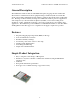
©2001 MaxStream, Inc. 24XStream™ Wireless OEM Module Manual v2.8 General Description The 24XStream-192/96 modules are 100-milliwatt frequency hopping wireless modules that allow wireless communication between equipment using a standard asynchronous serial data stream. The module is half-duplex and can sustain a continuous data stream at the specified data rate.
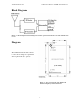
©2001 MaxStream, Inc. 24XStream™ Wireless OEM Module Manual v2.8 Block Diagram Figure 1 – Block diagram demonstrating basic module operation and data flow for both transmit and receive. Diagram 2.8250 The 24XStream data module connects to a host device using an 11 pin header and a 4 pin header (0.1” spaced). [TOP VIEW] Figure 2 – Top view diagram of the 24XStream module with pin layout and dimensions.
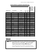
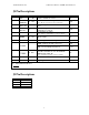
©2001 MaxStream, Inc. 24XStream™ Wireless OEM Module Manual v2.8 J1 Pin Descriptions Pin No. 1 2 3 4 5 Pin Name _____ CTS SLEEP (PWRDN) DO (Data Out) DI (Data In) RTS/CMD I/O Type O PU Description Clear to Send flow control Active low I PU Can be used to enter Sleep Mode high O PU I I PD RESET I PU 7 RXLED O 8 ___ TX/PWR O _______ CONFIG I PU* ________ 6 9 (See “Modes of Operation” section for details.
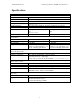
©2001 MaxStream, Inc. 24XStream™ Wireless OEM Module Manual v2.8 Specifications X24-009 X24-019 General Frequency Range Type Frequency Control Transport Protocol 2.40 to 2.4835 GHz, unlicensed ISM Band Frequency Hopping Spread Spectrum Transceiver Direct FM Various Monitoring and Addressing Modes – see “Networking and Addressing” section Channel Capacity Serial Data Interface Serial Interface Baud Rate Hops through 25 channels. Features 7 different hop sequences.
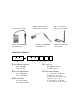
©2001 MaxStream, Inc. 24XStream™ Wireless OEM Module Manual v2.8 Product Listing X24-009NM, X24-019NM MMCX – Wire Antenna SMA – No Antenna X24-009WM, X24-019WM X24-009NS, X24-019NS ¼ Wave Antenna MMCX ½ Wave Antenna MMCX ½ Wave Antenna SMA A09-QBMM-3-P6I A09-HBMM-7-P6I A09-HASM-675 Module Part Numbers • ‚ ƒ „ … • Operating Frequency „ Connector ‚ Over-Air Baud Rate … Temperature Rating X09 – 900 MHz X24 – 2.
©2001 MaxStream, Inc. 24XStream™ Wireless OEM Module Manual v2.8 2.
©2001 MaxStream, Inc. 24XStream™ Wireless OEM Module Manual v2.8 Serial Port Operation The 24XStream modules come equipped with a CMOS-level asynchronous serial port. Through this serial port, the 24XStream can communicate directly with any device having a UART interface, or with a PC, or other RS-232 port, via the MaxStream interface board. By connecting the 24XStream to a host device’s serial port, the host device becomes empowered to communicate wirelessly with ease.
©2001 MaxStream, Inc. 24XStream™ Wireless OEM Module Manual v2.8 Data enters the 24XStream the DI pin as an asynchronous serial signal. The serial signal is idle (high) when no data is being transmitted. Each data packet consists of a start bit (low), 8 data bits, and a stop bit (high) as shown below in Figure 4. The 24XStream modules transfer exactly 8-bits over the air.
©2001 MaxStream, Inc. 24XStream™ Wireless OEM Module Manual v2.8 There are three cases in which the data buffer may become full. 1) Since the 9600 and 19200-baud modules support serial interface rates from 2400-57600 bits/second, the serial data rate could be configured at a higher rate than the module’s over-the-air baud rate. If this happens, long serial data streams can cause the data buffer to become momentarily full, causing *CTS to de-assert.
©2001 MaxStream, Inc. 24XStream™ Wireless OEM Module Manual v2.8 Modes of Operation The 24XStream wireless module features several modes of operation that allow the module to be responsive to data and yet utilize minimum power. The figure below shows these modes and is followed by a comprehensive look into each mode and the necessary conditions for the 24XStream module to transition from one mode to another.
©2001 MaxStream, Inc. 24XStream™ Wireless OEM Module Manual v2.8 Sent Data: Group Data into Packets: Figure 5a – Transmit Mode description. Figure 5b – Generation of data packets. Data Validity To verify data integrity, a 16-bit cyclic redundancy check (CRC) is computed for the transmitted data and attached to the end of each data packet before transmission. The receiver will then compute the CRC on all incoming data. Any received data that has an invalid CRC is discarded.
MaxStream, Inc. 24XStream Wireless Module Manual v2.8 The module will remain in Receive Mode until an error is detected in the received data, or no more data is detected, at which point, the module transitions to Idle Mode. If serial data was stored in the data buffer while the module was in Receive Mode, the data will be transmitted after the module returns to Idle Mode.
MaxStream, Inc. Sleep Settings No Sleep Mode Pin Sleep 24XStream Wireless Module Manual v2.8 Transition to Sleep Return to Idle Mode Mode None. The module remains in Idle Mode. (Default Setting) High on SLEEP pin Low on SLEEP pin. (pin 2). Serial Port Sleep Automatic transition after a user-defined period of module inactivity (no transmitting or receiving of data). Set by ST command.
MaxStream, Inc. 24XStream Wireless Module Manual v2.8 period can be set by adjusting the ST parameter (see the ‘ST’ command in “24XStream Command Table”). The module remains in Sleep Mode for a user-defined period of time ranging from 0.5 seconds to 8 seconds (adjustable using ‘SM’ command as described in “24XStream Command Table” section). After this period of time, the module returns to Idle Mode and listens for a valid data packet.
MaxStream, Inc. 24XStream Wireless Module Manual v2.8 Command Mode Command Mode allows several features, including the power-down and addressing options, to be configured. These adjustable parameters offer greater flexibility to designers in configuring the module to fit specific design criteria. There are three ways to enter Command Mode: 1) Assert RTS/CMD and send a binary command. 2) Send the sequence “+++” to send AT commands. 3) Assert (low) the *CONFIG pin and turn the power switch off and back on.
MaxStream, Inc. 24XStream Wireless Module Manual v2.8 To query the current value of a particular command, send the corresponding AT command without any parameters (carriage return is still sent). The response will be the current value of that command reported as a hexadecimal number. The following example demonstrates basic AT Command functionality in the 24XStream module. Example: This example will change the user-defined Module Address to 1A0D (HEX) and check the current value of the SM command.
MaxStream, Inc. 24XStream Wireless Module Manual v2.8 Commands can be queried for their current value by sending the command logically ORed with the value 80H (hexadecimal) with RTS/CMD asserted. When this binary value is sent (with no parameters) the current value of the command will be sent back, through the DO pin. NOTE: For the 24XStream module to recognize a Binary command, the RT command must be issued from AT Command Mode to enable binary programming.
MaxStream, Inc. 24XStream Wireless Module Manual v2.8 Factory Default Parameters Returned Description # Bytes Binary Command # AT Command 24XStream Command Table DT 0 V4.08 Set the Module Address. (Only Address value modules with the same address can Range: 0 – FFFFH communicate.) 2 0 SM 1 Adjust Sleep Mode setting. 0 – No Sleep Mode 1 – Pin Sleep 2 – Serial Port Sleep 3 – Cyclic 0.5 second sleep 4 – Cyclic 1.0 second sleep 5 – Cyclic 2.0 second sleep 6 – Cyclic 4.
12 Transmit header time Time in tenths of seconds for the long header. Range: 0 – 0xFF 1 FH 13 Force header on next transmit NA NA NA RE 14 Restore default configuration NA NA NA ER 15 Set Receive Error Count Value of error count. This value is reset to 0 after every reset it is not non-volatile 2 0 GD 16 Set Receive Good Count Value of good count. This value is reset to 0 after every reset it is not non-volatile 2 0 HP 17 Set Network number.
Parameters Factory Default Description Returned 24XStream Wireless Module Manual v2.8 # Bytes Binary Command # AT Command MaxStream, Inc. RT 22 V4.10 RTS/CMD Control 0 – No binary commands accessed with RTS/CMD. 1 – Binary commands are sent when RTS/CMD is asserted. 1 0 SY 23 V4.12 Set Sync Timer. This time represents the time that the transmitter and receiver stay in sync after receiving or sending data.
MaxStream, Inc. 24XStream Wireless Module Manual v2.8 Networking and Addressing The 24XStream modules utilize three levels of addressing to communicate between modules. This networking hierarchy is depicted in Figure 8 below. Only modules with the matching addresses are able to communicate. The three methods of addressing are: Vendor Identification number, Networks and Module Addresses. Figure 8 – Layout of a typical network configuration.
MaxStream, Inc. 24XStream Wireless Module Manual v2.8 Module Address Module Addresses and Module Address Masks provide another level of addressing among 24XStream modules. Each module in a network can be configured with a 16-bit Module Address to establish selective communications within a network. This address is set to one of 65535 values using the “DT” command. The default Module Address is 0000H. All modules with the same Module Address can transmit and receive data among themselves.
MaxStream, Inc. 24XStream Wireless Module Manual v2.8 F0F0H. There are three different ways that Module A can receive packets from other modules. 1) This module could receive packets from other modules with a Transmitter Module Address of 00FFH. 2) Since the Receiver Module Address Mask is set to F0F0H, logically “ with the Receiver Module Address yields “0XFX” (HEX) where the ‘X’ values can be anything.
MaxStream, Inc. 24XStream Wireless Module Manual v2.8 Electrical Characteristics DC Characteristics Vcc=4.75V to 5.25V Symbol VIL VIH Parameter Condition Min Input Low Voltage Input High Voltage All input signals ________ (Except RESET) Input High Voltage Output Low Voltage Output High Voltage Input Leakage Current I/O Pin VIH2 VOL VOH IIL Input Leakage Current I/O Pin IIH ________ (RESET) IOL =20mA Vcc=5V IOH =-3mA Vcc=5V Max Units -0.5 0.3*Vcc V 0.6*Vcc Vcc+0.5 V 0.9*Vcc Vcc+0.
MaxStream, Inc. 24XStream Wireless Module Manual v2.8 Cyclic Sleep Mode Timings Symbol TÄS TSL Description Time when module is listening for a valid header to start receiving data. Time where the 24XStream is in its low power cyclic sleep. This time is adjustable using the SM command. X24-019 100 ms X24-009 100 ms 0.5 seconds 1.0 seconds 2.0 seconds 4.0 seconds 8.0 seconds 0.5 seconds 1.0 seconds 2.0 seconds 4.0 seconds 8.0 seconds 0.6 seconds 1.1 seconds 2.1 seconds 4.1 seconds 8.1 seconds 0.
MaxStream, Inc. 24XStream Wireless Module Manual v2.8 FCC Qualifications IMPORTANT: The 24XStream module has been certified as a module by the FCC for integration into OEM products without further certification being necessary (as per FCC section 2.1091.) The OEM must satisfy the following requirements in order to comply with FCC regulations: 1) The system integrator must ensure that the external label provided with this device is placed on the outside of the final product.
MaxStream, Inc. 24XStream Wireless Module Manual v2.8 Using the 24XStream Development Kit Introduction: Use this development kit to experience the extended range and ease of use of the MaxStream 24XStream module. This module transmits data at either 9600 or 19200 bits per second (see FCC label on module shield) in the license-free 2.4 GHz ISM band. See how simple it is to communicate with the module using asynchronous serial communications by following the instructions below.
MaxStream, Inc. e. 24XStream Wireless Module Manual v2.8 following: Bits per second: 19200; Data bits: 8; Parity: None; Stop Bits: 1 and Flow Control: Hardware (See figure 3). Click OK. (Set the Bits per second to 9600 if you are using 24XStream-96 modules) Both computers are now set up and ready to communicate. 3. Test Connection a. Place cursor in HyperTerminal window of Computer 1 and type a message.
MaxStream, Inc. 24XStream Wireless Module Manual v2.8 Glossary AT commands – A set of commands that can be used to customize and configure the 24XStream module to meet specific needs. AT commands are sent via a serial communications program such as HyperTerminal. Binary commands – Another set of commands used to configure the 24XStream module. Binary commands are sent with RTS/CMD asserted. The RT command must be used to enable binary programming prior to using binary commands.
MaxStream, Inc. 24XStream Wireless Module Manual v2.8 Half-duplex – Radios that operate in halfduplex are able to either transmit data or receive data at a given time, but cannot do both simultaneously. The 24XStream is half-duplex. When one module is transmitting, all modules (with the same VID) within range listen to the transmission and will only transmit once the transmission is complete. Hardware flow control – See “Flow control”.
MaxStream, Inc. 24XStream Wireless Module Manual v2.8 settings are available and can be configured using the SM command. SLEEP pin – If Pin Sleep is enabled, the SLEEP pin (Pin 2) determines if the module is in Sleep Mode or Idle Mode. See “Pin Transmission Latency – Time required to send a packet of data. This value is dependent on the number of bytes being sent and the baud rate of the module.
MaxStream, Inc. 24XStream Wireless Module Manual v2.8 Index AC characteristics…………….. 27-28 Antennas……………………….7, 9 AT commands…………………18-19 Binary commands…………….. 19-20 Binary programming………….. 20 Command mode………………. 18 Command table……………….. 21-23 CONFIG pin…………………...13 CTS pin……………………….. 6, 11-12 Current Consumption………….7 Cyclic redundancy check (CRC) 14 Cyclic sleep……………………16-17 Data packet generation………...13-14 Data validity…………………...14 DC characteristics…………….. 27 DI pin………………………….