
User's Manual

©2001 MaxStream, Inc. 24XStream™ Wireless OEM Module Manual v2.8
8
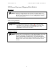
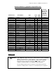
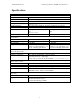
J1 Pin Descriptions
Pin No. Pin Name I/O Type Description Active
1
_____
CTS
O PU Clear to Send flow control low
2
SLEEP
(PWRDN)
I PU
Can be used to enter Sleep Mode
(See “Modes of Operation” section for details.)
high
3
DO
(Data Out)
O PU
Data leaving the module that is sent to the
host
high
4
DI
(Data In)
I
Data entering the 24XStream module to be
transmitted over the air
high
5 RTS/CMD I PD
Command mode enable
(See “Binary Command Mode” section for details.)
high
6
________
RESET
I PU Reset module low
7 RXLED O Indicates good RF data reception high
PWR - Indicates module powered on high
8
___
TX/PWR
O
___
TX - Asserted during transmission
low
9
_______
CONFIG
I PU*
Hold low during power up or reset - forces
ASCII command mode. DO NOT TIE TO
MICROPROCESSOR!
(See “Serial Port Operation” section for details.)
low
10 VCC I +5 VDC -
11 GND - Signal ground -
PU – 10kÙ Pull-Up Resistor
PD – 10kÙ Pull-Down Resistor
_________
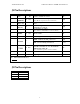
J2 Pin Descriptions
Pin Signal
1 GND
2 GND
3 GND
4 GND