
User's Manual


9XTend™ OEM RF Module - Product Manual v2.x6x
© 2010 Digi Internatonal, Inc. 6
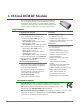
Pin Signals
Figure 1-01. XTend OEM RF Module Pin Numbers
* RF module has 10K internal pull-up resistor
Note: When integrating the module with a Host PC board, all lines not used should be left disconnected (floating).
Table 1-03. Pin Signal Descriptions
(Low-asserted signals distinguished with a horizontal line over signal name.)
Pin
Number
Mnemonic I/O
High Impedance
during Shutdown
Must
Connect
Function
1GND- - yesGround
2 VCC I - yes Power: 2.8 - 5.5 VDC
3
GPO2 /
RX LED
Oyes -
General Purpose Output 2: <Default (CD=2)> Pin is driven low. Refer to the CD
Command [p24] for other configuration options.
RX LED: Pin is driven high during RF data reception; otherwise, the pin is driven
low. Refer to the CD Command [p24] to enable.
4 TX
_PWR O yes -
Transmit_Power: Pin pulses low during RF transmission; otherwise, the pin is
driven high to indicate power is on and the module is not in Sleep or Shutdown
Mode.
5DIIyes yes
Data In: Serial data entering the module (from the UART host). Refer to the Serial
Communications [p9] section for more information.
6DOOyes -
Data Out: Serial Data exiting the module (to the UART host). Refer to the Serial
Communications [p9] section for more information.
7 SHDN
Ino yes
Shutdown: Pin is driven high during operation and low during Shutdown.
Shutdown enables the lowest power mode (~5 μA) available to the module. Refer
to the Shutdown Mode [p14] section for more information.
8 GPI2 / SLEEP I yes -
General Purpose Input 2: reserved for future use
SLEEP: By default, SLEEP is not used. To configure this pin to enable Sleep
Modes, refer to the Sleep Mode [p14], SM Command [p37] & PW Command [p32]
sections.
9
GPO1 / CTS
/
RS-485 TX_EN
Oyes -
General Purpose Output 1: reserved for future use
CTS
(Clear-to-Send): <Default (CS=0)> When pin is driven low, the UART host
is permitted to send serial data to the module. Refer to the Serial Communications
[p9] & CS Command [p25] sections for more information.
RS-485 Transmit Enable: To configure this pin to enable RS-485 half and full-
duplex communications. Refer to the Serial Communications [p9] & CS Command
[p25] sections.
10
GPI1 / RTS
/
CMD
Iyes -
General Purpose Input 1: reserved for future use
RTS
(Request-to-Send): By default, is not used. To configure this pin to
regulate the flow of serial data exiting the module, refer to the Serial
Communications [p9] & RT Command [p36] sections.
CMD (Command): By default, CMD is not used. To configure this pin to enable
binary command programming, refer to the Binary Commands [p17] & RT
Command [p36] sections.
11 CONFIG
/ RSSI
I* no -
Configuration: Pin can be used as a backup method for entering Command
Mode during power-up. Refer to the Command Mode [p17] section for more
information.
O* no -
Receive Signal Strength Indicator: By default, pin is used as an RSSI PWM
output after at the conclusion of the power-up sequence. Refer to the RP
Command [p35] for more information. The PWM output is 2.8V-level.
tcennoc ton od / devreser02-21