
User's Manual


9XTend™ OEM RF Module - Product Manual v2.x6x
© 2010 Digi Internatonal, Inc. 72
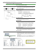
XTIB-R RS-232/485 Interface Board
Figure B-03. DIP Switch Seings of the XTIB-R (RS-232/485) Interface Board
B-01a. Config (Configuration) Switch
Figure B-01. Front View
The Config Switch provides an alternate method for entering into
Command Mode. To enter Command Mode at the module's default RF
data rate, hold the Configuration Switch down for two seconds.
B-01b. I/O & Power LEDs
The LEDs visualize gigantic status information and indicate module
activity as follows:
Yellow (top LED) = Serial Data Out (to host)
Green (middle) = Serial Data In (from host)
Red (bottom) =
Power/TX Indicator (Red light is on when
powered; it pulses on/off briefly during RF transmission.))
B-01c. DB-9 Serial Port
Standard female DB-9 (RS-232) connector. This connector can also
be used for RS-485 and RS-422 connections.
B-01d. RSSI LEDs
RSSI LEDs indicate the amount of fade margin present in an active
wireless link. Fade margin is defined as the difference between the
incoming signal strength and the module's receiver sensitivity.
3 LEDs ON = Very Strong Signal (> 30 dB fade margin)
2 LEDs ON = Strong Signal (> 20 dB fade margin)
1 LED ON = Moder
ate Signal (> 10 dB fade margin)
0 LED ON = Weak Signal (< 10 dB fade margin)
B-01e. Power Connector
7-28 VDC power connector (Center positive, 5.5/2.1mm)
Note: The XTIB-R interface board can accept voltages as low as 5V.
Contact MaxStream Technical Support to enable this option.
B-02a. DIP Switch
Figure B-02. Back View DIP Switch automatically configures the module to operate in differ-
ent modes during the power-on sequence. Each time the module
assembly (interface board + module) is powered-on, intelligence on
the board programs the attached module according to the positions
of
the DIP Switch.
Figure B-03 illustrates DIP Switch settings. Table B-02 summarizes
the configurations triggered by the positions of the DIP Switch.
B-01a.
Cong Switch
B-01b.
I/O & Power LEDs
B-01c.
DB-9 Serial Port
B-01d
RSSI LEDs
B-01e.
Power Connector
B-02a.
DIP Switch
Refer to the tables in the ‘Automatic
DIP Switch tions’ section
[next page] regarding congura-
tions triggered by the positions of
the DIP Switch (during power-up).