
User's Manual


9XTend™ OEM RF Module - Product Manual v2.x6x
© 2010 Digi Internatonal, Inc. 76
Interfacing Protocols
The XTend Module Assembly (XTend OEM RF Module mounted to the XTIB-R Interface Board) sup-
ports the following interfacing protocols:
RS-232
RS-485 (2-wire) Half-Duplex
RS-485 (4-wire) and RS-422
RS-232 Operation
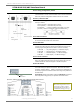
DIP Switch Settings and Serial Port Connections
Figure B- erugiF.11 B-12.
RS-232 DIP Switch Seings Pins used on the female RS-232 (DB-9) Serial Connector
* ‘X-CTU’ is soware that can be used to e the module. The soware includes a namin convention
where "GPI" stands for ‘General Purpose Input’ and "GPO" for ‘General Purpose Output’.
Table B-04. RS-232 Signals and their implementations on the XTend Module Assembly
(Low-asserted sils are distuished by horizontal line ov
er pin name.)
DB-9 Pin
RS-232
Name
X-CTU
Name*
Description Implementation
1 DCD GPO2 Data-Carrier-Detect Connected to DSR (pin6 of DB-9)
2 RXD DO Received Data Serial data exiting the module assembly (to host)
3 TXD DI Transmitted Data Serial data entering into the module assembly (from host)
4 DTR GPI2 Data-Terminal-Ready Can enable Power-Down on the module assembly
dnuorGlangiS dnuorG-DNG5
6 DSR GPO2 Data-Set-Ready Connected to DCD (pin1 of DB-9)
7 RTS
/ CMD GPI1
Request-to-Send /
Command Mode
Provides RTS flow control or enables Command Mode
8 CTS
GPO1 Clear-to-Send Provides CTS flow control
9 RI - Ring Indicator
Optional power input that is connected internally to the
positive lead of the front power connector
DIP Switch seins are read and applied
only while powerin-on.