
User's Manual


9XTend™ OEM RF Module - Product Manual v2.x6x
© 2010 Digi Internatonal, Inc. 77
Wiring Diagrams
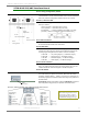
Figure B-13. DTE Device (RS-232, male DB-9 connector) wired to a DCE Module Assembly (female DB-9)
Figure B-14. DCE Module Assembly (female DB-9 connector) wired to a DCE Device (RS-232, male DB-9)
Sample Wireless Connection: DTE <--> DCE DCE <--> DCE
Figure B-15. Typical wireless link between DTE and DCE devices