
User's Manual


9XTend™ OEM RF Module - Product Manual v2.x6x
© 2010 Digi Internatonal, Inc. 79
RS-485 (4-wire) & RS-422 Operation
DIP Switch Settings and Serial Port Connections
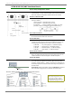
Figure B- erugiF.02 B-21.
RS-485 (4-wire) & RS-422 Pins used on the female RS-232 (DB-9)
DIP Switch laireSsgnitteS Connector
Note: Refer to Figures B-09 and B-10 for RJ-45 connector pin designations used in
RS-485/422 environments.
Table B-06. RS-485/422 (4-wire) Signals and their implementations on the XTend Module Assembly
DB-9 Pin
RS-485/422
Name
Description Implementation
2T- (TA)
Transmit Negative
Data Line
Serial data sent from the XTend Module Assembly
3R- (RA)
Receive Negative
Data Line
Serial data received by the XTend Module Assembly
dnuorGdnuorG langiSDNG5
7 R+ (RB)
Receive Positive
Data Line
Serial data received by the XTend Module Assembly
8 T+ (TB)
Transmit Positive
Data Line
Serial data sent from the XTend Module Assembly
9 PWR Power
Optional power input that is connected internally
to the front power connector
desu ton6 ,4 ,1
Figure B-22.
RS-485 (4-wire)& RS-422 w/ Termination (optional)
Termination is the 120 resistor between T+ and T-.
DIP Switch seings are read and applied only while powering-on.