
User's Manual


© 2010 Digi International Inc. 9
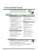
2. RF Module Operation
WARNING: When operating at 1 Watt power output, observe a minimum separation distance of 2' (0.6m) between
modules. Transmitting in close proximity of other modules can damage module front ends.
Serial Communications
The XTend OEM RF Modules interface to a host device through a TTL-level asynchronous serial
port. Through its serial port, the module can communicate with any UART voltage compatible
device or through a level translator to any serial device (For example: RS-232/485/422 or USB
interface board).
UART Data Flow
Devices that have a UART interface can connect directly to the pins of the RF module as shown in
the figure below.
Figure 2-01. System Data Flow Diagram in a UART-interfaced environment
(Low-asserted signals distinguished with horizontal line over signal name.)
Serial Data
Data enters the module UART through the pin 5 as an asynchronous serial signal. The signal
should idle high when no data is being transmitted.
Each data byte consists of a start bit (low), 8 data bits (least significant bit first) and a stop bit
(high). The following figure illustrates the serial bit pattern of data passing through the module.
Figure 2-02. UART data packet 0x1F (decimal number "31") as transmied through the RF module
Example Data Format is 8-N-1 (bits - parity - # of stop bits)
The module UART performs tasks, such as timing and parity chec
king, that are needed for data
communications. Serial communications depend on the two UARTs to be configured with compati-
ble settings (baud rate, parity, start bits, stop bits, data bits).