
User's Manual


CDH Communications
• Broadcast (promiscuous) networking protocol – data sent to the serial port on one
radio will be presented out of the serial port on all other radios that are within range
and have the same group code.
Connections
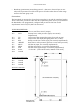
The Data Radio is connected to a host device using the 11 pin and the 4 pin berg headers.
These connections provide the radio with the required DC power source (+5V) and allow
the Data Radio to be programmed, configured and provide the I/O lines for the
asynchronous line level (TTL) RS-232 connection.
J1 PIN DESCRIPTIONS
J1-1 CTS Clear to send flow control (output)
J1-2 INT1 Interupt line to radio processor (input, not currently
implemented)
J1-3 TX Asyncronous data output (data going from radio to user)
J1-4 RX Asyncronous data input (data going from user to radio)
J1-5 RTS Ready to send flow control (input, not currently implemented)
J1-6 *RESET Reset line to radio processor (pull low to reset radio processor)
J1-7 MOSI SPI data in (input, not currently implemented)
J1-8 MISO SPI data out (output, not currently implemented)
J1-9 SCK SPI data clock (input/output, not currently implemented)
J1-10 Power +5 volts DC. (55mA in RX mode, 200mA in TX mode)
J1-11 Ground
J2 PIN DESCRIPTIONS
J2-1 Ground
J2-2 Ground
J2-3 Ground
J2-4 Ground
Antenna Connection
Female MMCX