
User Manual

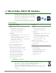


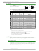


Table Of Contents
- 1. XBee®/XBee-PRO® RF Modules
- 2. RF Module Operation
- 3. RF Module Configuration
- Programming the RF Module
- Remote Configuration Commands
- Command Reference Tables
- Command Descriptions
- A1 (End Device Association) Command
- A2 (Coordinator Association) Command
- AC (Apply Changes) Command
- AI (Association Indication) Command
- AP (API Enable) Command
- AS (Active Scan) Command
- BD (Interface Data Rate) Command
- CA (CCA Threshold) Command
- CC (Command Sequence Character) Command
- CE (Coordinator Enable) Command
- CH (Channel) Command
- CN (Exit Command Mode) Command
- CT (Command Mode Timeout) Command
- D0 - D4 (DIOn Configuration) Commands
- D5 (DIO5 Configuration) Command
- D6 (DIO6 Configuration) Command
- D7 (DIO7 Configuration) Command
- D8 (DI8 Configuration) Command
- DA (Force Disassociation) Command
- DB (Received Signal Strength) Command
- DH (Destination Address High) Command
- DL (Destination Address Low) Command
- DN (Destination Node) Command
- DP (Disassociation Cyclic Sleep Period) Command
- EA (ACK Failures) Command
- EC (CCA Failures) Command
- ED (Energy Scan) Command
- EE (AES Encryption Enable) Command
- FP (Force Poll) Command
- FR (Software Reset) Command
- GT (Guard Times) Command
- HV (Hardware Version) Command
- IA (I/O Input Address) Command
- IC (DIO Change Detect) Command
- ID (Pan ID) Command
- IO (Digital Output Level) Command
- IR (Sample Rate) Command
- IS (Force Sample) Command
- IT (Samples before TX) Command
- IU (I/O Output Enable) Command
- KY (AES Encryption Key) Command
- M0 (PWM0 Output Level) Command
- M1 (PWM1 Output Level) Command
- MM (MAC Mode) Command
- MY (16-bit Source Address) Command
- NB (Parity) Command
- ND (Node Discover) Command
- NI (Node Identifier) Command
- NO (Node Discover Options) Command
- NT (Node Discover Time) Command
- P0 (PWM0 Configuration) Command
- P1 (PWM1 Configuration) Command
- PL (Power Level) Command
- PR (Pull-up Resistor) Command
- PT (PWM Output Timeout) Command
- RE (Restore Defaults) Command
- RN (Random Delay Slots) Command
- RO (Packetization Timeout) Command
- RP (RSSI PWM Timer) Command
- RR (XBee Retries) Command
- SC (Scan Channels) Command
- SD (Scan Duration) Command
- SH (Serial Number High) Command
- SL (Serial Number Low) Command
- SM (Sleep Mode) Command
- SO (Sleep Mode Command)
- SP (Cyclic Sleep Period) Command
- ST (Time before Sleep) Command
- T0 - T7 ((D0-D7) Output Timeout) Command
- VL (Firmware Version - Verbose)
- VR (Firmware Version) Command
- WR (Write) Command
- API Operation
- Appendix A: Agency Certifications
- Appendix B. Additional Information

XBee®/XBee‐PRO®RFModules‐802.15.4‐v1.xEx[2011.06.1]
©2011DigiInternatonal,Inc. 10
Electrical Characteristics
Table1‐03. DCCharacteristics(VCC=2.8‐3.4VDC)
Symbol Characteristic Condition Min Typical Max Unit
V
IL
Input Low Voltage All Digital Inputs - - 0.35 * VCC V
V
IH
Input High Voltage All Digital Inputs 0.7 * VCC - - V
V
OL
Output Low Voltage
I
OL
= 2 mA, VCC >= 2.7 V
--0.5V
V
OH
Output High Voltage
I
OH
= -2 mA, VCC >= 2.7 V
VCC - 0.5 - - V
II
IN
Input Leakage Current
V
IN
= VCC or GND, all inputs, per pin
- 0.025 1 µA
II
OZ
High Impedance Leakage Current
V
IN
= VCC or GND, all I/O High-Z, per pin
- 0.025 1 µA
TX Transmit Current VCC = 3.3 V -
45
(XBee)
215, 140
(PRO,
Int)
-mA
RX Receive Current VCC = 3.3 V -
50
(XBee)
55
(PRO)
-mA
PWR-DWN Power-down Current SM parameter = 1 - < 10 - µA
Table1‐04. ADCCharacteristics(Operating)
Symbol Characteristic Condition Min Typical Max Unit
V
REFH
VREF - Analog-to-Digital converter
reference range
2.08 -
V
DDAD*
V
I
REF
VREF - Reference Supply Current
Enabled - 200 - µA
Disabled or Sleep Mode - < 0.01 0.02 µA
V
INDC
Analog Input Voltage
1
1. Maximumelectricaloperatingrange,notvalidconversionrange.
*V
DDAD
isconnectedtoVCC.
V
SSAD
- 0.3
-
V
DDAD
+ 0.3
V
Table1‐05. ADCTiming/PerformanceCharacteristics
1
1. AllACCURACYnumbersarebasedonprocessorandsys tembeinginWAITstate(verylittleactivityandnoIOswitching)
andthatadequatelow‐passfilteringispresentonanaloginputpins(filterwith0.01μFto0.1μFcapac itorbetweenanalog
inputandVREFL).Failuretoobservetheseguidelinesmay
resultinsystemormicrocontrollernoisecausingaccuracyerrors
whichwillvarybasedonboardlayoutandthetypeandmagnitudeoftheactivity.
Datatransmissionandreceptionduringdataconversionmaycausesomedegradationofthesespecifications,dependingon
thenumberandtimingofpackets.Itisadvisabletotest
theADCsinyourinstallationifbestaccuracyisrequired.
Symbol Characteristic Condition Min Typical Max Unit
R
AS
Source Impedance at Input
2
2. R
AS
istherealportionoftheimpedanceofthenetworkdrivingtheanaloginputpin.Valuesgreaterthanthisamountmay
notfullychargetheinputcircuitryoftheATDresultinginaccuracyerror.
--
10
k
V
AIN
Analog Input Voltage
3
3. AnaloginputmustbebetweenV
REFL
andV
REFH
forvalidconversion.ValuesgreaterthanV
REFH
willconvertto$3FF.
V
REFL
V
REFH
V
RES
Ideal Resolution (1 LSB)
4
4. Theresolutionistheidealstepsizeor1LSB=(V
REFH
–V
REFL
)/1024
2.08V <
V
DDAD
< 3.6V
2.031 - 3.516 mV
DNL
Differential Non-linearity
5
5. Differentialnon‐linearityisthedifferencebetweenthecurrentcodewidthandtheidealcodewidth(1LSB).Thecurrent
codewidthisthedifferenceinthetransitionvoltagestoandfromthecurrentcod e.
- ±0.5 ±1.0 LSB
INL
Integral Non-linearity
6
6. Integralnon‐linearityisthedifferencebetweenthetransitionvoltagetothecurrentcodeandtheadjustedidealtransition
voltageforthecurrentcode.Theadjustedidealtransitionvoltageis(CurrentCode–1/2)*(1/((V
REFH
+E
FS
)–(V
REFL
+E
ZS
))).
- ±0.5 ±1.0 LSB
E
ZS
Zero-scale Error
7
7. Zero‐scaleerroristhedifferencebetweenthetransitiontothefirstvalidcodeandtheidealtransitiontothatcode.The
Idealtransitionvoltagetoagivencodeis(Code–1/2)*(1/(V
REFH
–V
REFL
)).
- ±0.4 ±1.0 LSB
F
FS
Full-scale Error
8
8. Full‐scaleerroristhedifferencebetweenthetransitiontothelastvalidcodeandtheidealtransitiontothatcode.Theideal
transitionvoltagetoagivencodeis(Code–1/2)*(1/(V
REFH
–V
REFL
)).
- ±0.4 ±1.0 LSB
E
IL
Input Leakage Error
9
9. Inputleakageerroriserrorduetoinputleakageacrosstherealportionoftheimpedanceofthenetworkdrivingtheanalog
pin.Reducingtheimpedanceofthenetworkreducesthiserror.
- ±0.05 ±5.0 LSB
E
TU
Total Unadjusted Error
10
- ±1.1 ±2.5 LSB