
User Manual


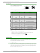


Table Of Contents
- 1. XBee®/XBee-PRO® RF Modules
- 2. RF Module Operation
- 3. RF Module Configuration
- Programming the RF Module
- Remote Configuration Commands
- Command Reference Tables
- Command Descriptions
- A1 (End Device Association) Command
- A2 (Coordinator Association) Command
- AC (Apply Changes) Command
- AI (Association Indication) Command
- AP (API Enable) Command
- AS (Active Scan) Command
- BD (Interface Data Rate) Command
- CA (CCA Threshold) Command
- CC (Command Sequence Character) Command
- CE (Coordinator Enable) Command
- CH (Channel) Command
- CN (Exit Command Mode) Command
- CT (Command Mode Timeout) Command
- D0 - D4 (DIOn Configuration) Commands
- D5 (DIO5 Configuration) Command
- D6 (DIO6 Configuration) Command
- D7 (DIO7 Configuration) Command
- D8 (DI8 Configuration) Command
- DA (Force Disassociation) Command
- DB (Received Signal Strength) Command
- DH (Destination Address High) Command
- DL (Destination Address Low) Command
- DN (Destination Node) Command
- DP (Disassociation Cyclic Sleep Period) Command
- EA (ACK Failures) Command
- EC (CCA Failures) Command
- ED (Energy Scan) Command
- EE (AES Encryption Enable) Command
- FP (Force Poll) Command
- FR (Software Reset) Command
- GT (Guard Times) Command
- HV (Hardware Version) Command
- IA (I/O Input Address) Command
- IC (DIO Change Detect) Command
- ID (Pan ID) Command
- IO (Digital Output Level) Command
- IR (Sample Rate) Command
- IS (Force Sample) Command
- IT (Samples before TX) Command
- IU (I/O Output Enable) Command
- KY (AES Encryption Key) Command
- M0 (PWM0 Output Level) Command
- M1 (PWM1 Output Level) Command
- MM (MAC Mode) Command
- MY (16-bit Source Address) Command
- NB (Parity) Command
- ND (Node Discover) Command
- NI (Node Identifier) Command
- NO (Node Discover Options) Command
- NT (Node Discover Time) Command
- P0 (PWM0 Configuration) Command
- P1 (PWM1 Configuration) Command
- PL (Power Level) Command
- PR (Pull-up Resistor) Command
- PT (PWM Output Timeout) Command
- RE (Restore Defaults) Command
- RN (Random Delay Slots) Command
- RO (Packetization Timeout) Command
- RP (RSSI PWM Timer) Command
- RR (XBee Retries) Command
- SC (Scan Channels) Command
- SD (Scan Duration) Command
- SH (Serial Number High) Command
- SL (Serial Number Low) Command
- SM (Sleep Mode) Command
- SO (Sleep Mode Command)
- SP (Cyclic Sleep Period) Command
- ST (Time before Sleep) Command
- T0 - T7 ((D0-D7) Output Timeout) Command
- VL (Firmware Version - Verbose)
- VR (Firmware Version) Command
- WR (Write) Command
- API Operation
- Appendix A: Agency Certifications
- Appendix B. Additional Information

XBee®/XBee‐PRO®RFModules‐802.15.4‐v1.xEx[2011.06.1]
©2011DigiInternatonal,Inc. 5
Specifications
*SeeAppendixAforregion‐specificcertificationrequirements.
Antenna Options: The ranges specified are typical when using the integrated Whip (1.5 dBi) and Dipole (2.1 dBi) anten-
nas. The Chip antenna option provides advantages in its form factor; however, it typically yields shorter range than the
Whip and Dipole antenna options when transmitting outdoors.For more information, refer to the "XBee Antennas" Knowl-
edgebase Article located on Digi's Support Web site
Table1‐01. SpecificationsoftheXBee®/XBee‐PRO®RFModules
Specification XBee XBee-PRO
Performance
Indoor/Urban Range Up to 100 ft (30 m)
Up to 300 ft. (90 m), up to 200 ft (60 m) International
variant
Outdoor RF line-of-sight Range Up to 300 ft (90 m)
Up to 1 mile (1600 m), up to 2500 ft (750 m)
international variant
Transmit Power Output
(software selectable)
1mW (0 dBm)
63mW (18dBm)*
10mW (10 dBm) for International variant
RF Data Rate 250,000 bps 250,000 bps
Serial Interface Data Rate
(software selectable)
1200 bps - 250 kbps
(non-standard baud rates also supported)
1200 bps - 250 kbps
(non-standard baud rates also supported)
Receiver Sensitivity -92 dBm (1% packet error rate) -100 dBm (1% packet error rate)
Power Requirements
Supply Voltage 2.8 – 3.4 V 2.8 – 3.4 V
Transmit Current (typical) 45mA (@ 3.3 V)
250mA (@3.3 V) (150mA for international variant)
RPSMA module only: 340mA (@3.3 V) (180mA for
international variant)
Idle / Receive Current (typical) 50mA (@ 3.3 V) 55mA (@ 3.3 V)
Power-down Current < 10 µA < 10 µA
General
Operating Frequency ISM 2.4 GHz ISM 2.4 GHz
Dimensions 0.960” x 1.087” (2.438cm x 2.761cm) 0.960” x 1.297” (2.438cm x 3.294cm)
Operating Temperature -40 to 85º C (industrial) -40 to 85º C (industrial)
Antenna Options
Integrated Whip Antenna, Integrated PCB Antenna,
U.FL Connector, RPSMA connector
Integrated Whip Antenna, Chip Antenna, U.FL
Connector, RPSMA connector
Networking & Security
Supported Network Topologies Point-to-point, Point-to-multipoint & Peer-to-peer
Number of Channels
(software selectable)
16 Direct Sequence Channels 12 Direct Sequence Channels
Addressing Options PAN ID, Channel and Addresses PAN ID, Channel and Addresses
Agency Approvals
United States (FCC Part 15.247) OUR-XBEE OUR-XBEEPRO
Industry Canada (IC) 4214A XBEE 4214A XBEEPRO
Europe (CE) ETSI ETSI (Max. 10 dBm transmit power output)*
Japan R201WW07215214
R201WW08215111 (Max. 10 dBm transmit power
output)*
Australia C-Tick C-Tick