
User Manual


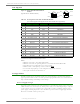


Table Of Contents
- 1. XBee®/XBee-PRO® RF Modules
- 2. RF Module Operation
- 3. RF Module Configuration
- Programming the RF Module
- Remote Configuration Commands
- Command Reference Tables
- Command Descriptions
- A1 (End Device Association) Command
- A2 (Coordinator Association) Command
- AC (Apply Changes) Command
- AI (Association Indication) Command
- AP (API Enable) Command
- AS (Active Scan) Command
- BD (Interface Data Rate) Command
- CA (CCA Threshold) Command
- CC (Command Sequence Character) Command
- CE (Coordinator Enable) Command
- CH (Channel) Command
- CN (Exit Command Mode) Command
- CT (Command Mode Timeout) Command
- D0 - D4 (DIOn Configuration) Commands
- D5 (DIO5 Configuration) Command
- D6 (DIO6 Configuration) Command
- D7 (DIO7 Configuration) Command
- D8 (DI8 Configuration) Command
- DA (Force Disassociation) Command
- DB (Received Signal Strength) Command
- DH (Destination Address High) Command
- DL (Destination Address Low) Command
- DN (Destination Node) Command
- DP (Disassociation Cyclic Sleep Period) Command
- EA (ACK Failures) Command
- EC (CCA Failures) Command
- ED (Energy Scan) Command
- EE (AES Encryption Enable) Command
- FP (Force Poll) Command
- FR (Software Reset) Command
- GT (Guard Times) Command
- HV (Hardware Version) Command
- IA (I/O Input Address) Command
- IC (DIO Change Detect) Command
- ID (Pan ID) Command
- IO (Digital Output Level) Command
- IR (Sample Rate) Command
- IS (Force Sample) Command
- IT (Samples before TX) Command
- IU (I/O Output Enable) Command
- KY (AES Encryption Key) Command
- M0 (PWM0 Output Level) Command
- M1 (PWM1 Output Level) Command
- MM (MAC Mode) Command
- MY (16-bit Source Address) Command
- NB (Parity) Command
- ND (Node Discover) Command
- NI (Node Identifier) Command
- NO (Node Discover Options) Command
- NT (Node Discover Time) Command
- P0 (PWM0 Configuration) Command
- P1 (PWM1 Configuration) Command
- PL (Power Level) Command
- PR (Pull-up Resistor) Command
- PT (PWM Output Timeout) Command
- RE (Restore Defaults) Command
- RN (Random Delay Slots) Command
- RO (Packetization Timeout) Command
- RP (RSSI PWM Timer) Command
- RR (XBee Retries) Command
- SC (Scan Channels) Command
- SD (Scan Duration) Command
- SH (Serial Number High) Command
- SL (Serial Number Low) Command
- SM (Sleep Mode) Command
- SO (Sleep Mode Command)
- SP (Cyclic Sleep Period) Command
- ST (Time before Sleep) Command
- T0 - T7 ((D0-D7) Output Timeout) Command
- VL (Firmware Version - Verbose)
- VR (Firmware Version) Command
- WR (Write) Command
- API Operation
- Appendix A: Agency Certifications
- Appendix B. Additional Information

XBee®/XBee‐PRO®RFModules‐802.15.4‐v1.xEx[2011.06.1]
©2011DigiInternatonal,Inc. 8
Recommended Pin Connections
The only required pin connections are VCC, GND, DOUT and DIN. To support serial firmware
updates, VCC, GND, DOUT, DIN, RTS, and DTR should be connected.
All unused pins should be left disconnected. All inputs on the radio can be pulled high with internal
pull-up resistors using the PR software command. No specific treatment is needed for unused out-
puts.
Other pins may be connected to external circuitry for convenience of operation including the Asso-
ciate LED pin (pin 15) and the commissioning button pin (pin 20). The Associate LED will flash dif-
ferently depending on the state of the module, and a pushbutton attached to pin 20 can enable
various deployment and troubleshooting functions without having to send UART commands.
If analog sampling is desired, VRef (pin 14) should be attached to a voltage reference.
Board Layout
XBee modules are designed to be self sufficient and have minimal sensitivity to nearby processors,
crystals or other PCB components. As with all PCB designs, Power and Ground traces should be
thicker than signal traces and able to comfortably support the maximum current specifications. No
other special PCB design considerations are required for integrating XBee radios except in the
antenna section.
Antenna Performance
Antenna location is an important consideration for optimal performance. In general, antennas radi-
ate and receive best perpendicular to the direction they point. Thus a vertical antenna's radiation
pattern is strongest across the horizon. Metal objects near the antenna may impede the radiation
pattern. Metal objects between the transmitter and receiver can block the radiation path or reduce
the transmission distance, so antennas should be positioned away from them when possible. Some
objects that are often overlooked are metal poles, metal studs or beams in structures, concrete (it
is usually reinforced with metal rods), vehicles, elevators, ventilation ducts, refrigerators, micro-
wave ovens, batteries, and tall electrolytic capacitors. If the XBee is to be placed inside a metal
enclosure, an external antenna should be used.
XBee units with the Chip or Integrated PCB Antenna should not be placed inside a metal enclosure
or have any ground planes or metal objects above or below the antenna. For best results, place
the XBee at the edge of the host PCB on which it is mounted. Ensure that the ground, power and
signal planes are vacant immediately below the antenna section. Digi recommends allowing a
"keepout" area, which is shown in detail on the next page.