
User Manual
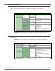


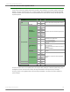
Table Of Contents
- 1. Overview
- 2. RF Module Operation
- 3. XBee ZigBee Networks
- Introduction to ZigBee
- ZigBee Stack Layers
- Networking Concepts
- ZigBee Application Layers: In Depth
- Coordinator Operation
- Router Operation
- End Device Operation
- Channel Scanning
- 4. Transmission, Addressing, and Routing
- 5. Security
- 6. Network Commissioning and Diagnostics
- 7. Managing End Devices
- 8. XBee Analog and Digital IO Lines
- 9. API Operation
- API Frame Specifications
- API UART Exchanges
- Supporting the API
- API Frames
- AT Command
- AT Command - Queue Parameter Value
- ZigBee Transmit Request
- Explicit Addressing ZigBee Command Frame
- Remote AT Command Request
- Create Source Route
- AT Command Response
- Modem Status
- ZigBee Transmit Status
- ZigBee Receive Packet
- ZigBee Explicit Rx Indicator
- ZigBee IO Data Sample Rx Indicator
- XBee Sensor Read Indicator
- Node Identification Indicator
- Remote Command Response
- Over-the-Air Firmware Update Status
- Route Record Indicator
- Many-to-One Route Request Indicator
- Sending ZigBee Device Objects (ZDO) Commands with the API
- Sending ZigBee Cluster Library (ZCL) Commands with the API
- Sending Public Profile Commands with the API
- 10. XBee Command Reference Tables
- 11. Module Support
- Appendix A: Definitions
- Appendix B: Agency Certifications
- Appendix C: Migrating from ZNet 2.5 to XBee ZB
- Appendix D: Additional Information

XBee®/XBee‐PRO®ZBRFModules
©2011DigiInternational,Inc. 113
ZigBee IO Data Sample Rx Indicator
Frame Type: 0x92
When the module receives an IO sample frame from a remote device, it sends the sample out the UART using
this frame type (when AO=0). Only modules running API firmware will send IO samples out the UART.
Frame Fields Offset Example Description
A
P
I
P
a
c
k
e
t
Start Delimiter 00x7E
Length MSB 1 0x00 Number of bytes between the length and the checksum
Frame-specific Data
LSB 2 0x14
Frame Type 30x92
64-bit Source
Address
MSB 4 0x00
64-bit address of sender
50x13
60xA2
70x00
80x40
90x52
10 0x2B
LSB 11 0xAA
16-bit Source
Network Address
MSB 12 0x7D
16-bit address of sender.
LSB 13 0x84
Receive Options 14 0x01
0x01 - Packet Acknowledged
0x02 - Packet was a broadcast packet
Number of Samples 15 0x01
Number of sample sets
included in the payload.
(Always set to 1)
Digital Channel Mask*
16 0x00 Bitmask field that indicates
which digital IO lines on the
remote have sampling
enabled (if any).
17 0x1C
Analog Channel
Mask**
18 0x02
Bitmask field that indicates
which analog IO lines on the
remote have sampling
enabled (if any).
Digital Samples (if
included)
19 0x00 If the sample set includes any digital IO lines
(Digital Channel Mask > 0), these two bytes
contain samples for all enabled digital IO lines.
DIO lines that do not have sampling enabled
return 0. Bits in these 2 bytes map the same as
they do in the Digital Channels Mask field.
20 0x14
Analog Sample
21 0x02 If the sample set includes any analog input lines
(Analog Channel Mask > 0), each enabled analog input
returns a 2-byte value indicating the A/D measurement
of that input. Analog samples are ordered sequentially
from AD0/DIO0 to AD3/DIO3, to the supply voltage.
22 0x25
Checksum 23 0xF5 0xFF - the 8 bit sum of bytes from offset 3 to this byte.
N/A N/A N/A CD/DIO
12
PWM/DI
O11
RSSI/DI
O10
N/A N/A
CTS/DI
O7
RTS/DI
O6
ASSOC/
DIO5
DIO4 AD3/DI
O3
AD2/DI
O2
AD1/DI
O1
AD0/DI
O0
Supply
Voltage
N/A N/A N/A AD3 AD2 AD1 AD0
*
**