
User Manual
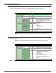


Table Of Contents
- 1. Overview
- 2. RF Module Operation
- 3. XBee ZigBee Networks
- Introduction to ZigBee
- ZigBee Stack Layers
- Networking Concepts
- ZigBee Application Layers: In Depth
- Coordinator Operation
- Router Operation
- End Device Operation
- Channel Scanning
- 4. Transmission, Addressing, and Routing
- 5. Security
- 6. Network Commissioning and Diagnostics
- 7. Managing End Devices
- 8. XBee Analog and Digital IO Lines
- 9. API Operation
- API Frame Specifications
- API UART Exchanges
- Supporting the API
- API Frames
- AT Command
- AT Command - Queue Parameter Value
- ZigBee Transmit Request
- Explicit Addressing ZigBee Command Frame
- Remote AT Command Request
- Create Source Route
- AT Command Response
- Modem Status
- ZigBee Transmit Status
- ZigBee Receive Packet
- ZigBee Explicit Rx Indicator
- ZigBee IO Data Sample Rx Indicator
- XBee Sensor Read Indicator
- Node Identification Indicator
- Remote Command Response
- Over-the-Air Firmware Update Status
- Route Record Indicator
- Many-to-One Route Request Indicator
- Sending ZigBee Device Objects (ZDO) Commands with the API
- Sending ZigBee Cluster Library (ZCL) Commands with the API
- Sending Public Profile Commands with the API
- 10. XBee Command Reference Tables
- 11. Module Support
- Appendix A: Definitions
- Appendix B: Agency Certifications
- Appendix C: Migrating from ZNet 2.5 to XBee ZB
- Appendix D: Additional Information

XBee®/XBee‐PRO®ZBRFModules
©2011DigiInternational,Inc. 114
Example: Suppose an IO sample is received with analog and digital IO, from a remote with a 64-
bit address of 0x0013A200 40522BAA and a 16-bit address of 0x7D84. If pin AD1/DIO1 is enabled
as an analog input, AD2/DIO2 and DIO4 are enabled as a digital inputs (currently high), and AD3/
DIO3 is enabled as a digital output (low) the IO sample is shown in the API example in the table
above.
XBee Sensor Read Indicator
Frame Type: 0x94
When the module receives a sensor sample (from a Digi 1-wire sensor adapter), it is sent out the UART using
this message type (when AO=0).
Example: Suppose a 1-wire sensor sample is received from a device with a 64-bit address of
0x0013A200 40522BAA and a 16-bit address of 0xDD6C. If the sensor sample was taken from a
1-wire humidity sensor, the API frame could look like this (if AO=0):
For convenience, let's label the A/D and temperature readings as AD0, AD1, AD2, AD3, and T. Using the data in
this example:
AD0 = 0x0002
AD1 = 0x00CE
AD2 = 0x00EA
AD3 = 0x0052
Frame Fields Offset Example Description
A
P
I
P
a
c
k
e
t
Start Delimiter 00x7E
Length MSB 1 0x00 Number of bytes between the length and the checksum
Frame-specific Data
LSB 2 0x17
Frame Type 30x94
64-bit Source
Address
MSB 4 0x00
64-bit address of sender
50x13
60xA2
70x00
80x40
90x52
10 0x2B
LSB 11 0xAA
16-bit Source
Network Address
MSB 12 0xDD
16-bit address of sender.
LSB 13 0x6C
Receive Options 14 0x01
0x01 - Packet Acknowledged
0x02 - Packet was a broadcast packet
1-Wire
Sensors
15 0x03
0x01 = A/D Sensor Read
0x02 = Temperature Sensor Read
0x60 = Water present (module CD pin low)
A/D Values
16 0x00
Indicates a two-byte value for each of four A/D sensors
(A, B, C, D)
Set to 0xFFFFFFFFFFFFFFFF if no A/Ds are found.
17 0x02
18 0x00
19 0xCE
20 0x00
21 0xEA
22 0x00
23 0x52
Temperature
Read
24 0x01
Indicates the two-byte value read from a digital
thermometer if present. Set to 0xFFFF if not found.
25 0x6A
Checksum 26 0x8B 0xFF - the 0x8 bit sum of bytes from offset 3 to this byte.