
User Manual


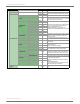


Table Of Contents
- 1. Overview
- 2. RF Module Operation
- 3. XBee ZigBee Networks
- Introduction to ZigBee
- ZigBee Stack Layers
- Networking Concepts
- ZigBee Application Layers: In Depth
- Coordinator Operation
- Router Operation
- End Device Operation
- Channel Scanning
- 4. Transmission, Addressing, and Routing
- 5. Security
- 6. Network Commissioning and Diagnostics
- 7. Managing End Devices
- 8. XBee Analog and Digital IO Lines
- 9. API Operation
- API Frame Specifications
- API UART Exchanges
- Supporting the API
- API Frames
- AT Command
- AT Command - Queue Parameter Value
- ZigBee Transmit Request
- Explicit Addressing ZigBee Command Frame
- Remote AT Command Request
- Create Source Route
- AT Command Response
- Modem Status
- ZigBee Transmit Status
- ZigBee Receive Packet
- ZigBee Explicit Rx Indicator
- ZigBee IO Data Sample Rx Indicator
- XBee Sensor Read Indicator
- Node Identification Indicator
- Remote Command Response
- Over-the-Air Firmware Update Status
- Route Record Indicator
- Many-to-One Route Request Indicator
- Sending ZigBee Device Objects (ZDO) Commands with the API
- Sending ZigBee Cluster Library (ZCL) Commands with the API
- Sending Public Profile Commands with the API
- 10. XBee Command Reference Tables
- 11. Module Support
- Appendix A: Definitions
- Appendix B: Agency Certifications
- Appendix C: Migrating from ZNet 2.5 to XBee ZB
- Appendix D: Additional Information

XBee®/XBee‐PRO®ZBRFModules
©2011DigiInternational,Inc. 119
Route Record Indicator
Frame Type: 0xA1
The route record indicator is received whenever a device sends a ZigBee route record command. This is used
with many-to-one routing to create source routes for devices in a network.
Example: Suppose device E sends a route record that traverses multiple hops en route to data
collector device A as shown below.
A B C D E
If device E has the 64-bit and 16-bit addresses of 0x0013A200 40401122 and 0x3344, and if devices B, C, and
D have the following 16-bit addresses:
B = 0xAABB
C = 0xCCDD
D = 0xEEFF
The data collector will send the above API frame out its UART.
Frame Fields Offset Example Description
A
P
I
P
a
c
k
e
t
Start Delimiter 00x7E
Length MSB 1 0x00
Number of bytes between the length and the checksum
LSB 2 0x13
Frame-specific Data
Frame Type 30xA1
64-bit Source
Address
MSB 4 0x00
64-bit address of the device that
initiated the route record.
50x13
60xA2
70x00
80x40
90x40
10 0x11
LSB 11 0x22
Source (updater)
16-bit Address
12 0x33 16-bit address of the
device that initiated the
route record.
13 0x44
Receive Options 14 0x01
0x01 - Packet Acknowledged.
0x02 - Packet was a broadcast.
Number of Addresses 15 0x03
The number of addresses in the
source route (excluding source
and destination).
Address 1
16 0xEE
(neighbor of
destination)
17 0xFF
Address 2 (closer hop
18 0xCC
Address of intermediate hop
19 0xDD
Address n (neighbor
of source)
20 0xAA
Two bytes per 16-bit address.
21 0xBB
Checksum 22 0x80 0xFF - the 8 bit sum of bytes from offset 3 to this byte.