High Performance V.34 28,800 BPS Internal FAX/Data Modem User's Manual Contents Section One Section Two Section Three Section Four Section Five Section Six Section Seven Section Eight Section Nine Introduction ............................ 1 Installation .............................. 1 AT Command Set ................... 6 S Register Summary ............ 11 Result Codes .......................... 12 Troubleshooting .................... 15 Specifications ........................ 17 Support And Service ....
Section One - Introduction The 28.8 Kbps Series FAX/Data Modem products connect your computer to all popular high speed modems available today. The modem supports the V.34 protocol to supply the highest speed connections possible. It also uses V.42 or MNP 2-4 error correction for flawless connections and V.42bis or MNP 5 data compression for increased throughput. This manual describes the hardware installation procedures for your new modem product.
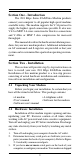
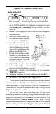
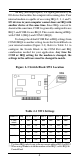
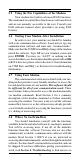
Figure 2-1 Common Serial Ports male connector set to COM1 on IRQ4. Reconfigure the modem to either COM3/IRQ5 or COM4/IRQ2 (refer to Table 2-1 in Section 2.4). 4. Remove your computer's cover (refer to your computer's owner manual). Figure 2-2 5. Select any available half-card Expansion slot, and then remove the slot cover (refer to Figure 2-2). Slots 6. Carefully slide the internal modem into the slot you have chosen, applying even pressure until the modem is completely seated in the slot. 7.
Panel, double-click on Ports. Click once on the icon for the Com port you have set your modem to. Click the Settings button. Click the Advanced button. The Base I/O Port Address should already be set by Windows to the COM port address used by the modem (refer to Table 2-1). Change the Interrupt Request Line (IRQ) to match the IRQ on the modem. If you have set the modem to COM4/IRQ2, do not select IRQ2. You will need to set the IRQ in Control Panel to IRQ9 for Windows to recognize the modem.
An IRQ (interrupt request) is a signal generated by an I/O device that notifies the computer of incoming data. Your internal modem is capable of accessing IRQs 2, 3, 4, and 5. I/O devices in your computer cannot share an IRQ with another device at the same time. Since IRQs can not be shared at the same time, COM 3 is generally configured to use IRQ 5, and COM 4 to use IRQ 2. This avoids sharing of IRQs with COM 1 (IRQ4) and COM 2 (IRQ3).
2.5 Using the Fax Capabilities of the Modem Your modem has built-in advanced FAX functions. The commands to control these functions are software driven and are not normally accessible to the user. Consult your FAX software manual about procedures on using FAX features. 2.6 Testing Your Modem After Installation In order to test your modem you should be familiar with your communication software. Load and set up your communication software and enter into “terminal mode.
commonly asked questions and problems. Section Three - AT Command Set 3.1 Executing Commands Commands are accepted by the modem while it is in Command Mode. Your modem is automatically in Command Mode until you dial a number and establish a connection. Commands may be sent to your modem from a PC running communication software or any other terminal devices. Your modem is capable of data communication at rates of: 300, 1200, 2400, 4800, 9600, 14400, 19200, 38400, 57600, and 115200 bps.
B6 B7 B8 B9 B10 B11 B12 B13 B14 B15 2400 bps connection only 4800 bps connection only 9600 bps connection only 14400 bps connection only 16800 bps connection only 19200 bps connection only 21600 bps connection only 24000 bps connection only 26400 bps connection only 28800 bps connection only D_ 0 - 9, A-D, # and * L last number redial P pulse dialing T touch-tone dialing W wait for second dial tone , pause @ wait for five seconds of silence ! flash ; return to Command Mode after dialing DS=n Dial one o
O1 O2 O3 Return to Data Mode and initiate an equalizer retrain Same as O1 with speed fall forward Same as O1 with speed fall backward P Set Pulse dial as default Q0 Q1 Modem sends responses Modem does not send responses Sr? Read and display value in register r. Sr=n Set register r to value n (n = 0-255).
&F4 &F5 with &D0) Same as &F2 except for Macintosh computers (&F2 with &D0) Same as &F except V.
%Ln Set transmit level to -n dBm Default = 12.(n=0-15) %M0 %M1 %M2 Autodetect V.34 and V.FC negotiation signals Autodetect V.34 negotiation signals only Autodetect V.FC negotiation signals only %P0 %P1 Disable Power-on Auto-connect Enable Power-on Auto-connect %S0 %S1 %S2 Disable Call-back Security Enable Call-back Security with password check Enable Password check only \P=x Stores password x (x = ASCII characters 1 through 127 excluding “?”, maximum 7 characters) into nonvolatile RAM MNP/V.42/V.
\Kn Set break control (n= 0-5). Default is 5 \N0 \N1 \N2 \N3 \N4 \N5 \N6 Normal data-link only Direct data-link only MNP data link only MNP or Normal data link V.42 data link only V.42 or MNP data link only V.
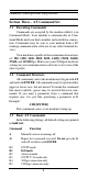
Table 4-1 S - Registers Register Function Range/units Default S0 S1 S2 S3 S4 S5 S6 S7 S8 S9 S10 S11 S12 S13 S14 Auto-answer Ring 0-255/rings Ring counter 0-255/rings Escape code character 0-127/ASCII Carriage return character 0-127/ASCII Line feed character 0-127/ASCII Backspace character 0-32, 127/ASCII Dial tone wait time 2-255 /seconds Remote carrier wait time 1-255/seconds Comma pause time 0-255/seconds Carrier detect response time 1-255/0.1 second Carrier loss time 1-255/0.
CONNECT 9600 CONNECT 12000 CONNECT 14400 CONNECT 16800 CONNECT 19200 CONNECT 21600 CONNECT 24000 13 14 15 60 61 62 63 CONNECT 26400 CONNECT 28800 CONNECT 38400 CONNECT 57600 CONNECT 115200 CONNECT 1200/75 CONNECT 75/1200 64 65 66 67 68 48 49 EXTENDED RESPONSE CODES CONNECT 300/MNP CONNECT 1200/MNP CONNECT 2400/MNP CONNECT 4800/MNP CONNECT 7200/MNP CONNECT 9600/MNP CONNECT 12000/MNP CONNECT 14400/MNP CONNECT 16800/MNP CONNECT 19200/MNP CONNECT 21600/MNP CONNECT 24000/MNP CONNECT 26400/MNP CONNECT 28800/M
CONNECT 300/V42 CONNECT 1200/V42 CONNECT 2400/V42 CONNECT 4800/V42 CONNECT 7200/V42 CONNECT 9600/V42 CONNECT 12000/V42 CONNECT 14400/V42 CONNECT 16800/V42 CONNECT 19200/V42 CONNECT 21600/V42 CONNECT 24000/V42 CONNECT 26400/V42 CONNECT 28800/V42 CONNECT 38400/V42 CONNECT 57600/V42 CONNECT 115200/V42 CONNECT 300/V42BIS CONNECT 1200/V42BIS CONNECT 2400/V42BIS CONNECT 4800/V42BIS CONNECT 7200/V42BIS CONNECT 9600/V42BIS CONNECT 12000/V42BIS CONNECT 14400/V42BIS CONNECT 16800/V42BIS CONNECT 19200/V42BIS CONNECT 2
Section Six - Troubleshooting This section describes some of the common problems you may encounter while using your modem. If you can not resolve your difficulty after reading this chapter, contact your dealer or vendor for assistance. Modem does not respond to commands. 1. Make sure the modem is not configured with a conflicting COM port and IRQ setting (see Section 2.4). Your modem can not be configured as COM1 (default) if another device in your system is also configured as COM1.
sounds noisy, you may have difficulty connecting to the remote device. Modem makes a connection but no data appears on your screen. 1. The remote system may be waiting to receive your data before it begins. Try pressing the ENTER key a few times. 2. Make sure the correct data format (data bits, stop bits, and parity bits) and flow control (RTS/CTS) are being used. 3. Make sure the correct terminal emulation mode is being used (see communication software manual). 4.
Section Seven - Specifications Communication Std. V.34, V.FC, V.32bis, V.32, V.29, V.27ter, V.22bis, V.23, V.22, V.21, V.17, Bell212/ 103 Data Compression: V.42bis/MNP5 Error Correction: V.
operation of your equipment. If they do, you will be notified in advance to give you an opportunity to maintain uninterrupted telephone service. The FCC prohibits this equipment to be connected to party lines or coin-telephone service. In the event that this equipment should fail to operate properly, disconnect the equipment from the phone line to determine if it is causing the problem. If the problem is with the equipment, discontinue use and contact your dealer or vendor.
Before installing this equipment, users ensure that it is permissible to be connected to the facilities of the local telecommunications company. The equipment must also be installed using an acceptable method of connection. The customer should be aware that compliance with the above conditions may not prevent degradation of service in some situations. Repairs to certified equipment should be made by an authorized Canadian maintenance facility designated by the supplier.