R213M05H.qxd 6/26/2006 9:04 AM Page 1 ® OXYGEN MONITOR MODEL OM-25ME (OM-25ME-L) USER’S GUIDE AND OPERATING INSTRUCTIONS R213M05 Rev.
R213M05H.
R213M05H.qxd 6/26/2006 9:04 AM Page i Manufacturer: Maxtec, Inc European Representative Airox S.A.
R213M05H.qxd 6/26/2006 9:04 AM Page ii PREFACE This manual describes the function, operation and maintenance of the Maxtec Model OM-25ME and OM-25ME-L oxygen monitors. Notes are included where differences may occur between the two monitors. As members of Maxtec's MAXO2 line of oxygen analyzers and monitors, the OM-25ME utilizes the Maxtec MAX-250E oxygen sensor and is engineered for fast response, maximum reliability and stable performance.
R213M05H.qxd 6/26/2006 9:04 AM Page iii To avoid explosion, do not operate the Oxygen monitor in the presence of flammable anesthetics or in an atmosphere of explosive gases. Operating the oxygen monitor in flammable or explosive atmospheres may result in fire or explosion. Never allow an excess length of cable near the patient’s head or neck, as such could result in strangulation. Secure excess cable to the bed rail or suitable object.
R213M05H.qxd 6/26/2006 9:04 AM Page iv The OM-25ME-L™ oxygen monitor has been manufactured with a low alarm setting adjustable down to 15% This change is within the guidelines set forth in ASTM Specification F1462-93. The OM-25ME-L™ is labeled to indicate this feature. Classification: Protection against electric shock: Internally powered equipment.
R213M05H.qxd 6/26/2006 9:04 AM Page v TABLE OF CONTENTS 1. SYSTEM OVERVIEW ........................................... 1.1 Base Unit Description .............................. 1.2 Components Description ........................ 1.3 MAX-250E Oxygen Sensor .......................... 2. SET-UP PROCEDURE ......................................... 2.1 Battery Installation ................................... 2.2 Calibrating the MAXO2 Monitor ................. 2.2.1 Before You Begin ............................
R213M05H.qxd 6/26/2006 9:04 AM Page vi 1. SYSTEM OVERVIEW 1.1 Base Unit Description The MAXO2 (Model OM-25ME) provides unparalleled performance and reliability, due to an advanced design that includes the following features and operational benefits. • Fast-responding, oxygen-specific, galvanic sensor that achieves 90% of final value in approximately 15 seconds at room temperature. • Extra-life oxygen sensor of approximately 900,000 O2 percent hours (minimum 2 years in most applications).
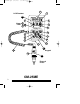
R213M05H.qxd 1.2 6/26/2006 9:04 AM Page 1 Components Description (please refer to page 3) A LCD Readout 1 3 1/2-Digit Display- The 3 1/2-digit liquid crystal display (LCD) provides direct readout of oxygen concentrations in the range of 0-100%. It also displays "CAL" when the calibration mode is entered. 2 "%" Sign- In the calibration mode, the "%" sign flashes every second.
R213M05H.
R213M05H.qxd 6/26/2006 9:04 AM Page 3 B Alarm LEDs 8 Low Alarm LED- In a low alarm condition, the red "LOW ALARM" LED will flash each second, accompanied by the alarm beeper. 9 High Alarm LED- In a high alarm condition, the red "HIGH ALARM" LED will flash each second, accompanied by the alarm beeper. C Keypad 10 ON/OFF Key- (after Calibration) This key is used to turn the instrument on or off.
R213M05H.qxd 6/26/2006 9:04 AM Page 4 13 ↑ and ↓ Keys- The ↑ and ↓ arrow keys are used in conjunction with the CALIBRATE key to calibrate the unit or in conjunction with the LOW SET and HIGH SET keys to adjust the alarm settings. When used after pressing the CALIBRATE key, pressing the ↑ or ↓ key will raise or lower the displayed oxygen value in .1% increments. When either of these keys are held down for more than 1 second, the display will scroll at a rate of .4% per second.
R213M05H.qxd 1.3 6/26/2006 9:04 AM Page 5 MAX-250E Oxygen Sensor MAX-250E oxygen sensors offer quick response, stability and extra life on the order of 900,000 percent hours. The MAX-250E is a galvanic, partial pressure sensor that is specific to oxygen. It consists of two electrodes (a cathode and an anode), a teflon membrane and an electrolyte. Oxygen diffuses through the teflon membrane and immediately reacts electrochemically at a gold cathode.
R213M05H.qxd 6/26/2006 9:04 AM Page 6 2. SET-UP PROCEDURE 2.1 Battery Installation All MAXO2 units are powered by two, AA, alkaline batteries (2 x 1.5 Volts) and are shipped without the batteries installed. The battery compartment is accessible from the back side of the unit. To install the batteries: 1) With the thumb, press down on the center of the battery compartment cover and slide the cover off of the instrument case. 2) Install the two, AA, alkaline batteries (2 x 1.
R213M05H.qxd 6/26/2006 9:04 AM Page 7 be performed when the geographic elevation at which the product is being used changes by more than 500 feet. The sensor is best calibrated while mounted in the industry standard, 15mm I.D. “T” adapter. As in normal operation, the oxygen sensor responds best when installed in a vertical position with the sensor facing down.
R213M05H.qxd 6/26/2006 9:04 AM Page 8 6) Use the ↑ and ↓ arrow keys to adjust the displayed oxygen concentration to the level of the known concentration. Pressing the arrow keys changes the value in .1% increments. If the keys are held down for more than 1 second the display will scroll at a rate of .4% per second. Note: If 10 seconds elapse between key actuations, the system will store the latest calibration value and will revert to normal operation.
R213M05H.qxd 6/26/2006 9:04 AM Page 9 To use this function: 1) Place the external probe in room air. 2) Press the LOCK\UNLOCK key to unlock the keypad. 3) Press and hold down the CALIBRATE key. When the "%" sign starts to flash, press the ↓ arrow key to set the calibration value to 20.9%. 4) Release both the CALIBRATE key and the ↓ key. The unit will automatically enter the “LOCKED” condition and return to normal operation. 2.2.
R213M05H.qxd 6/26/2006 9:04 AM Page 10 Pressure Effect Readings from the MAXO2 Monitor are proportional to the partial pressure of oxygen. The partial pressure of Oxygen (PO2) is equal to the percentage of oxygen (%O2) times the absolute pressure (AP) at which the sample enviroment is measured. (PO2=%O2 x AP). Thus the readings are proportional to the concentration if the pressure is held constant.
R213M05H.qxd 6/26/2006 9:04 AM Page 11 3. OPERATING INSTRUCTIONS 3.1 Alarm Setting Procedure 3.1.1 Low Alarm Setting To adjust the low alarm setting: 1) Press the LOCK/UNLOCK key to unlock the keypad. 2) Press the LOW SET key. The "LOW" icon will start to flash. 3) Use the ↑ and ↓ arrow keys to set the low alarm to the desired value. Pressing the arrow keys changes the value in 1% increments. If the keys are held down for more than 1 second the display will scroll at a rate of 4% per second.
R213M05H.qxd 6/26/2006 9:04 AM Page 12 The high alarm value cannot be set closer than 1% from the low alarm value due to ASTM specifications. For example, if the low alarm is set at 50%, the system will not accept a high alarm setting less than 51%. Setting the high alarm to 100% turns off or deactivates the high alarm. 4) When the high alarm value is set, press the HIGH SET key again to accept the high alarm setting and return to normal operation.
R213M05H.qxd 6/26/2006 9:04 AM Page 13 4. SENSOR REMOVAL AND REPLACEMENT The OM-25ME is shipped with a new MAX-250E oxygen sensor installed. Although the sensor has a very long expected life, eventually the sensor will require replacement. Removing or installing a sensor, when necessary, is a very simple procedure. To remove and install a new sensor: 1) Grasp the sensor in one hand and, with the other hand, unscrew the cable connector counter-clockwise at the sensor.
R213M05H.qxd 6/26/2006 9:04 AM Page 14 5. PROBLEM SOLVING • If the "LOW BAT" icon is displayed on the LCD readout at any time, the batteries should be replaced as quickly as possible. • When the unit is in the power on mode and the LCD displays "000%," the sensor is not connected properly. The "ATTACH SENSOR" icon will also appear on the display. Check the sensor connection and if the condition persists, contact Maxtec's Customer Service Department. • If, at any time, "ErX" (i.e. Er1, Er4, etc.
R213M05H.qxd 6/26/2006 9:04 AM Page 15 7. SPECIFICATIONS 7.1 Base Unit Specifications Measurement Range: 0.0-100% Resolution: 0.1% Accuracy and Linearity: ±1% of full scale at constant temperature, R.H. and pressure when calibrated at full scale. Total Accuracy: ±3% Actual Oxygen Level over full operating temperature range.
R213M05H.qxd 6/26/2006 9:04 AM Page 16 8. APPLICATIONS 8.1 Exposure to Anesthetic Gases Because of the unique chemistry of the oxygen sensors provided with the MAXO2 Monitor, there are no significant effects when exposed to commonly used anesthetic gases, however, the monitor is not designed for exposure to flammable gas mixtures. (See WARNING page i) 8.
R213M05H.qxd 6/26/2006 9:04 AM Page 17 8.3 Calibration Errors The MAXO2 Monitors have a self test feature built into the software to detect faulty calibrations. During calibration, if the signal from the oxygen sensor is outside the limits stored within the instrument’s memory, a flashing “CAL Er” is displayed. The error code is displayed to indicate that either the sensor should be replaced or that there is a fault in the calibration process. A few simple hints can prevent calibration errors.
R213M05H.qxd 6/26/2006 9:04 AM Page 18 Additionally, gas streams of high humidity may tend to condense on the sensor. Condensation on the sensor may eventually affect performance. For this reason, it is recommended that the sensor be mounted in a vertical position, facing downward to prevent condensate from flowing onto the sensing surface.
R213M05H.qxd 6/26/2006 9:04 AM Page 19 9.
R213M05H.qxd 6/26/2006 9:04 AM Page 20 10. WARRANTY The MAXO2 Monitor is designed for medical oxygen delivery equipment and systems. Under normal operating conditions, Maxtec warrants the MAXO2 Monitor to be free from defects of workmanship or materials for a period of two (2) years from the date of shipment from Maxtec, provided that the unit is properly operated and maintained in accordance with Maxtec’s operating instructions.
R213M05H.
R213M05H.qxd 6/26/2006 9:04 AM Page 22 Maxtec, Inc. 6526 South Cottonwood Street Salt Lake City, UT 84107 General Tel: 801-266-5300 Toll Free Dial: 800-748-5355 FAX: 801-270-5590 Home Page: http://www.maxtecinc.com email: sales@maxtecinc.