High Performance V.90/V.34+/V.42bis 56K BPS PCI Internal Voice/FAX/Data/ Speakerphone Modem User's Manual Contents Section One - Introduction .......................... 1 Section Two - Installation ............................. 1 Section Three - AT Command Set ............... 6 Section Four - S Registers ........................ 13 Section Five - Result Codes ...................... 14 Section Six - Troubleshooting .................... 15 Section Seven - Support and Service .........
The information contained in this manual has been validated at the time of this manual's production. The manufacturer reserves the right to make any changes and improvements in the product described in this manual at any time and without notice. Consequently the manufacturer assumes no liability for damages incurred directly or indirectly from errors, omissions or discrepancies between the product and the manual. All registered trademarks are the property of their respective owners.
Section One - Introduction The MaxTech XPVS56P/C PCI Plug and Play Data, Fax, Voice Speakerphone Modem connects your computer to all popular high speed modems available today. The modem utilizes V.90 (56Kbps) technology to provide increased download speeds using regular telephone lines. The modem incorporates Plug and Play for ease of installation. This manual describes the hardware installation procedures for your new modem.
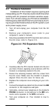
2.3 Hardware Installation Installation of this modem requires opening and manipulating your PC. Exercise caution at all times when working with AC powered and static-sensitive equipment. Turn off and unplug your PC before installation. Discharge any static electricity from your body by touching any grounded metal surface of the PC system, such as its power supply cover. 1. Turn off and unplug your computer from the AC outlet. 2. Remove your computer's cover (refer to your computer's owner's manual).
2.4 Hardware Configuration The version of Windows 9x you have will determine which set of dialog boxes is presented to you when installing the modem in Windows 9x. Proceed to one of the following sections, depending on your Windows 9x's diaglog box: • Section 2.4.1 when Windows 95 starts for the first time after card installation, it detects the modem and it displays the New Hardware Found dialog box • Section 2.4.1.
2.4.1.1 Windows 95 Release 4.00.950 B When Windows 95 starts for the first time after card installation, it detects the modem and displays the Update Device Driver Wizard. Insert the driver disk into the disk drive and click “Next.” Windows will find the driver on the driver disk. Click “Finish. Windows 95 may request its own installation disks or CD for some files. Insert the Windows 95 disks or CD as required. Windows will now find a second device on the modem.
software. Consult the software manual for information on using these and other parameters/features. 115,200 bps; 8 data bits; no parity; 1 stop bit; RTS/CTS flow control set to “on;” initialization string: AT&F Select a “Generic Class 1” modem type in your fax software Note that your software must be configured to communicate with the modem on the same COM port and IRQ line used by the modem. 2.
2.8 Where To Go From Here You should familiarize yourself with the functions available from the included software by reading its manual. You will be accessing most, if not all, of the modem's functions from this software. You may also use any other commercially available communication software with the modem. Read Section 3 only if you are interested in accessing the modem manually, and not through the included software. Section 4 and 5 contain reference material, and can be skipped.
3.3 Basic AT Commands In the following listings, all default settings are printed in bold text. Command Function A Manually answer incoming call A/ Repeat last command executed. Do not precede A/ with AT or follow with ENTER AT Appears at the beginning of every command line B_ B0 B1 B2 B3 CCITT mode Bell mode V.23 at 1200/75 V.
I5 I6 I7 I8 I10 Modem chip hardware configuration Country code Board manufacturer firmware version Modem firmware version Modem board configuration L_ L0 L1 L2 L3 Low speaker volume Low speaker volume Medium speaker volume High speaker volume M_ M0 M1 Internal speaker off Internal speaker on until carrier detected Internal speaker always on Internal speaker on until carrier detected and off while dialing M2 M3 N_ N0 N1 Connect only at DTE rate Automatic rate negotiation O_ O0 O1 Return to Data
X1 X2 X3 X4 Y_ Y0 Y1 Z_ Z0 Z1 3.
&Q_ &Q0 Modem in asynchronous mode &S_ &S0 Force DSR Signal High (ON) &S1 DSR is off in command mode, on in on-line mode &T_ &T0 Ends test in progress &T1 Perform Local Analog Loopback Test &U_ &U0 Enable Trellis Coding @ V.32 &U1 Disable Trellis Coding @ V.
%E1 V.22bis auto-retrain enabled %E2 Enable line signal quality monitor and fallback/fallforward %G_ %G0 Enable Auto Fall Forward/Back %G1 Disable Auto Fall Forward/Back -C_ -C0 -C1 -C2 3.5 Calling tone disabled 1300hz calling tone V.8 and 1300hz calling tones enabled MNP/V.42/V.42bis Commands %An Set auto-reliable fallback character to n (where n = 0 to 127, ASCII). Requires the \C2 setting.
Default is 5 \N_ \N0 \N1 \N2 \N3 \N4 Normal data-link only Normal data-link only MNP data link only V.42/MNP/Normal data link V.42 data link only \Q0 \Q1 \Q2 Turn off flow control XON/XOFF software flow control CTS signal unidirectional hardware flow control RTS/CTS signal bi-directional hardware flow control \O Initiate reliable link during a normal link \Q_ \Q3 \T n Inactivity timer, where n = 0 to 90 minutes.
+FTH=n +FTM=n +FTS=n 3.
Table 4-1 S - Registers Register S0 S1 S2 S3 S4 S5 S6 S7 S8 S9 S10 S11 S12 S14 S16 S18 S21 S22 S23 S25 S27 S30 S31 S33 Function Range/units Default Auto-answer Ring Ring counter Escape code character Carriage return character Line feed character Backspace character Dial tone wait time Remote carrier wait time Comma pause time Carrier detect time Carrier loss time Touch-tone dialing speed Esc.
CONNECT 33600 CONNECT 38400 CONNECT 42666 CONNECT 45333 CONNECT 48000 CONNECT 50666 CONNECT 53333 CONNECT 56000 CONNECT 57600 DATA RINGBACK 66 28 36 38 42 53 55 57 18 35 45 CONNECT CONNECT CONNECT CONNECT CONNECT CONNECT CONNECT CONNECT CONNECT FAX 37333 41333 44000 46666 49333 52000 54666 57333 115200 34 35 37 39 43 54 56 58 31 33 Section Six - Troubleshooting This section describes some of the common problems you may encounter while using your modem.
Modem does not dial. 1. Make sure the modem is connected to a working phone line. Replace the modem with a working phone to ensure that the phone line is working. Modem dials but does not connect. 1. Make sure the IRQ setting is identical on both the modem AND the software. Modem and software must be configured identically. 2. Make sure the phone line is working properly. Replace the modem with a regular phone and dial the number.
Modem experiences bursts of errors or suddenly disconnects while communicating with a remote modem. 1. Make sure Call Waiting is turned off. 2. Make sure the phone line does not exhibit excess noise. Section Seven - Support and Service In the unlikely event you experience difficulty in the use of this product, we suggest you: (1) consult the Troubleshooting section of this guide and (2) consult with your dealer.
the FCC. Your telephone company may make changes in its facilities, equipment, operations, or procedures that could affect proper operation of your equipment. If they do, you will be notified in advance to give you an opportunity to maintain uninterrupted telephone service. The FCC prohibits this equipment to be connected to party lines or coin-telephone service.
Before installing this equipment, users ensure that it is permissible to be connected to the facilities of the local telecommunications company. The equipment must also be installed using an acceptable method of connection. The customer should be aware that compliance with the above conditions may not prevent degradation of service in some situations. Repairs to certified equipment should be made by an authorized Canadian maintenance facility designated by the supplier.