High Performance K56Plus/V.34+/V.42bis 56K BPS Plug & Play Internal FAX/Data Modem User's Manual Contents Section One - Introduction .......................... 1 Section Two - Installation ............................ 1 Section Three - AT Command Set .............. 7 Section Four - S Registers ........................ 12 Section Five - Result Codes ..................... 14 Section Six - Troubleshooting ................... 15 Section Seven - Support and Service ....... 16 Appendix A - Specifications .......
The information contained in this manual has been validated at the time of this manual's production. The manufacturer reserves the right to make any changes and improvements in the product described in this manual at any time and without notice. Consequently the manufacturer assumes no liability for damages incurred directly or indirectly from errors, omissions or discrepancies between the product and the manual. All registered trademarks are the property of their respective owners.
Section One - Introduction This 56 Kbps* Plug and Play FAX/Data Modem connects your computer to all popular high speed modems available today. The modem incorporates “K56Plus” (56Kbps) technology to provide increased download speeds using regular telephone lines. The modem incorporates Plug and Play for ease of installation. This manual describes the hardware installation procedures for your new modem.
Proceed to Section 2.3 now if you have everything required. If you have neither 2A or 2B above, you have two options to provide Plug and Play functionality to your PC. 1. Install Windows 95 or, 2. If running DOS or Windows 3.x, configure the modem using the included modem driver. Instructions for installing this driver are included in the text file called README.1ST on the Windows 95 driver disk. The README.1ST file can be viewed by loading it into any wordprocessor or any text editor (i.e.
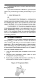
4. Carefully slide the internal modem into the slot you have chosen, applying even pressure until the modem is completely seated in the slot. 5. Fasten the retaining bracket with the screw from the slot cover. Make sure the modem is properly aligned. Store the slot cover for future use. 6. Replace the computer cover and plug in your computer. 7. Connect the telephone cable from the modem's LINE connector to the telephone wall jack. 8. Optionally, connect your telephone to the modem's PHONE connector. 9.
• Section 2.4.1.1 when Windows 95 starts for the first time after card installation, it detects the modem and it displays the New Hardware Found dialog box • Section 2.4.1.2 when Windows 95 starts for the first time after card installation, it detects the modem and it displays the Update Device Driver Wizard. 2.4.1.1 Windows 95 Release 4.00.950 When Windows 95 starts for the first time after card installation, it detects the modem and displays the New Hardware Found dialog box.
2.4.2 Configuring in a Plug and Play System without Windows 95 When this modem is installed in a Plug and Play system without Windows 95, the computer's BIOS will assign a COM port and IRQ line to the modem. Proceed to Section 2.5, Software Installation/ Configuration. 2.4.3 Configuring in a Non-Plug and Play System Computers without native Plug and Play capabilities require the use of the included modem driver. If you have not already installed this driver, refer to the file README.
Note that your software must be configured to communicate with the modem on the same COM port and IRQ line used by the modem. 2.6 Testing Your Modem After Installation In order to test your modem you should be familiar with your communication software. Load and set up your communication software and enter into “terminal mode.” Make sure that the COM Port and IRQ settings of the modem match the software. Type AT on your terminal screen and press ENTER. You may see “AT”, “AATT” or nothing on the screen.
contain reference material, and can be skipped. If you have difficulties getting your modem to work, read Section 6 - Troubleshooting to find answers to commonly asked questions and problems. Section Three - AT Command Set 3.1 Executing Commands Commands are accepted by the modem while it is in Command Mode. Your modem is automatically in Command Mode until you dial a number and establish a connection.
D_ L P T W , @ ! ; DS=n E_ 0 - 9, A-D, # and * last number redial pulse dialing touch-tone dialing wait for second dial tone pause wait for five seconds of silence flash return to Command Mode after dialing Dial one of the four telephone numbers (n=0-3) stored in the modem’s nonvolatile memory.
Sr=n Set register r to value n (n = 0-255). T Set Tone Dial as default V_ V0 V1 Numeric responses Word responses W_ W0 W1 Report DTE speed only Report line speed, error correction protocol, and DTE speed. Report DCE speed only W2 X_ X0 X1 X2 X3 X4 Y_ Y0 Y1 Z_ Z0 Z1 Hayes Smartmodem 300 compatible responses/blind dialing.
&K5 &K6 Enable transparent XON/XOFF flow control Enable both RTS/CTS and XON/XOFF flow control &L_ &L0 &M_ &M0 Asynchronous operation &P_ &P0 &P1 &P2 &P3 Modem is set up for dial-up operation US setting for off-hook-to-on-hook ratio UK and Hong Kong off-hook-to-on-hook ratio Same as &P0 setting but at 20 pulses per minute Same as &P1 setting but at 20 pulses per minute &R_ &R0 &R1 Reserved CTS operates per flow control requirements &S_ &S0 &S1 Force DSR Signal High (ON) DSR off in command mode
%E_ %E0 Disable auto-retrain %E1 Enable auto-retrain +MS? Displays the current Select Modulation settings +MS=? Displays a list of supported Select Modulation options +MS=a,b,c,d.e,fSelect modulation where: a=0, 1, 2, 3, 9, 10, 11, 56, 64, 69; b=0-1; c=30056000; d=300-56000; e=0-1; and f=01. A, b, c, d, e, f default=56, 1, 300, 56000, 0, 0. Parameter “a” specifies the modulation protocol desired where: 0=V.21, 1=V.22, 2=V.22bis, 3=V.23, 9=V.32, 10=V.32bis, 11=V.
&Q_ &Q0 &Q5 &Q6 Direct data link only (same as \N1) V.42 data link with fallback options Normal data link only (same as \N0) \A_ \A0 \A1 64-character maximum MNP block size 128-character maximum MNP block size 192-character maximum MNP block size 256-character maximum MNP block size \A2 \A3 \Bn Send a 1/10 second line break to the modem, where n = 1 to 9. At normal connect, the default is 3 \Kn Set break control, where n= 0 to 2.
Table 4-1 S - Registers Register Function Range/units Default S0 S1 S2 S3 S4 S5 S6 S7 S8 S9 S10 S11 S12 S13 S14 Auto-answer Ring Ring counter Escape code character Carriage return character Line feed character Backspace character Dial tone wait time Remote carrier wait time Comma pause time Carrier detect response time Carrier loss time Touch-tone dialing speed Escape character guard time Reserved Echo, response, dialing, originate/answer S15 Reserved S16 Modem tests S17 Reserved S18 Length of modem tes
S49-81 Reserved S82 Break options 3, 7, or 128 S83-85 Reserved S86 Connection failure code 0, 4, 5, 9, 12, 13, 14 S87-S90 Reserved S91 Transmit attenuation 0-15/dBm S92 Fax attenuation 0-15/dBm S95 Extended result code optionsBit-mapped register 128 10 10 0 Section Five - Result Codes OK 0 RING 2 ERROR 4 NO DIALTONE 6 NO ANSWER 8 CONNECT 2400 10 CONNECT 9600 12 CONNECT 12000 14 CONNECT 19200 16 CONNECT 34000 166 CONNECT 38000 168 CONNECT 40000 169 CONNECT 44000 171 CONNECT 48000 173 CONNECT 52000 175 CON
Section Six - Troubleshooting This section describes some of the common problems you may encounter while using your modem. If you can not resolve your difficulty after reading this chapter, contact your dealer or vendor for assistance. Modem does not respond to commands. 1. Make sure the communication software is configured to “talk” to the modem on the correct COM port and IRQ setting (same COM port and IRQ setting as the modem).
used. 2. Make sure the correct terminal emulation mode is being used (see communication software manual). High pitch tone is heard whenever you answer the phone. 1. Make sure Auto-Answer is turned off. Your modem is factory configured to NOT auto-answer. Issue AT&F to factory reset your modem. Modem experiences errors while communicating with a remote modem. 1. Make sure the DTE speed is the same as the modem connection speed when in Direct Mode. 2.
Appendix A - Specifications Communication Std. K56FLEX (56Kbps), V.34, V.32bis, V.32, V.29, V.27ter, V.22bis, V.23, V.22, V.21, V.17, Bell212/103 Data Compression: V.42bis/MNP5 Error Correction: V.42/MNP2-4 Host Interface: 16 bit PC bus COM ports: 1, 2, 3, 4 IRQ lines: 3, 4, 5, 7, 9, 10, 11, 12, 15 FAX Group: Group III Send/Receive Standard FAX Command set: EIA/TIA-578 Service Class 1 Transmit level: -11 dBm +/- 1 dB Receiver Sensitivity: -39 dBm (V.
The FCC prohibits this equipment to be connected to party lines or coin-telephone service. In the event that this equipment should fail to operate properly, disconnect the equipment from the phone line to determine if it is causing the problem. If the problem is with the equipment, discontinue use and contact your dealer or vendor. The FCC also requires the transmitter of a FAX transmission be properly identified (per FCC Rules Part 68, Sec. 68.381 (c) (3)).
permissible to be connected to the facilities of the local telecommunications company. The equipment must also be installed using an acceptable method of connection. The customer should be aware that compliance with the above conditions may not prevent degradation of service in some situations. Repairs to certified equipment should be made by an authorized Canadian maintenance facility designated by the supplier.