High Performance V.32bis/V.42bis 14,400 BPS Internal FAX/Voice/Data Modem Featuring Advanced Speakerphone Functions User's Manual Contents Section One Section Two Section Three Section Four Section Five Section Six Section Seven Section Eight Section Nine Introduction ........................... 1 Installation ............................. 1 AT Command Set .................. 6 S Register Summary ........... 12 Result Codes ......................... 13 Troubleshooting ...................
Section One - Introduction The 14.4 Kbps Series FAX/Voice/Data Modem connect your computer to all popular high speed modems available today. This manual describes the hardware installation procedures for your new modem product. Additional information on AT commands and S-registers are provided so that your system can be customized for a particular operating environment. Section Two - Installation This section will provide step by step instructions on how to install your new 14.4 Kbps FAX/Voice/Data modem.
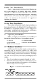
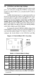
. If you have one or more serial ports on the back of your computer, reconfigure your modem. Your modem is shipped set to COM1 on IRQ4. Reconfigure the modem to either COM3/IRQ5 or COM4/IRQ2 (refer to Table 2-1 in Section 2.4). Figure 2-2 4. Remove your computer's cover Expansion (refer to your computer's owner Slots manual). 5. Select any available half-card slot, and then remove the slot cover (refer to Figure 2-2). 6.
Address should already be set by Windows to the COM port address used by the modem (refer to Table 2-1). Change the Interrupt Request Line (IRQ) to match the IRQ on the modem. If you have set the modem to COM4/IRQ2, do not select IRQ2. You will need to set the IRQ in Control Panel to IRQ9 for Windows to recognize the modem. (In an operating system designed for 286 or better machines, IRQ 9 is equivalent (redirected) to IRQ2.
2.4 COM Port and Interrupt Settings If your computer is equipped with one or more serial ports, you will need to change the COM Port setting on the modem (to either COM 3 or 4), or disable the PC's built-in COM port. An IRQ (interrupt request) is a signal generated by an I/O device that notifies the computer of incoming data. Your internal modem is capable of accessing IRQs 2, 3, 4, and 5. I/O devices in your computer cannot share an IRQ with another device at the same time.
combination needed for your application. Any time the COM or IRQ setting for the modem is changed, the settings in the software must be changed to match. 2.5 Using Fax, Voice, and Speakerphone Capabilities of the Modem Your modem has built-in advanced FAX, Voice, and Speakerphone functions. These functions are accessed through software. Please consult your FAX/Voice/Speakerphone software manual about procedures on using these functions.
provide a user friendly method of accessing the functions you need (i.e. dialing or answering calls). 2.8 Where To Go From Here You should familiarize yourself with the functions available from the included software by reading its manual. You will be accessing most, if not all, of the modem's functions from this software. You may also use any other commercially available communication software with the modem.
3.3 Basic AT Commands In the following listings, all default settings are printed in bold text. Command Function A Manually answer incoming call A/ Repeat last command executed.
M2 M3 Internal speaker always on Internal speaker on until carrier detected and off while dialing N_ N0 N1 Connect only at DTE rate Automatic rate negotiation O_ O0 O1 Return to Data Mode Return to Data Mode and initiate an equalizer retrain P Set Pulse dial as default Q_ Q0 Q1 Sr? r=0-30 Read and display value in register r Sr=n Modem sends responses Modem does not send responses Set register r to value n (r=0-30; n=0-255) T Set Tone Dial as default V_ V0 V1 Numeric responses Word resp
&D1 &D3 Modem returns to Command Mode after DTR toggle Modem hangs up, returns to the Command Mode after DTR toggle Resets modem after DTR toggle &F_ &F Recall factory default configuration &G_ &G0 &G1 &G2 Guard tone disabled 550 Hz guard tone 1800 Hz guard tone &M_ &M0 Asynchronous operation &P_ &P0 &D2 &P1 United States setting for off-hook (make) to-on-hook (break) ratio UK and Hong Kong off-hook (make)-to-onhook (break) ratio &S_ &S0 &S1 Force DSR Signal High (ON) DSR is off in command
&Zn=x n=0-3 Store telephone number x into non-volatile RAM %E_ %E0 V.22bis auto-retrain disabled %E1 V.22bis auto-retrain enabled %G_ %G0 Enable Auto Fall Forward/Back %G1 Disable Auto Fall Forward/Back 3.5 MNP/V.42/V.42bis Commands %An n=0127 %C_ %C0 Disable MNP Class 5 data compression %C1 Enable MNP Class 5 data compression \A_ \A0 \A1 \A2 \A3 \Bn n=1-9 Send a 1/10 second line break to the modem, where n = 1 to 9.
\N4 \O \Q_ V.42 data link only Initiate reliable link during a normal link \Q0 \Q1 \Q2 \Q3 Turn off flow control XON/XOFF software flow control CTS signal unidirectional hardware flow control RTS/CTS signal bi-directional hardware flow control \Tn Inactivity timer, where n = 0 to 90 minutes.
+FRH= Receive HDLC data +FRHM= Receive data +FRS=
Table 4-1 S - Registers Register S0 S1 S2 S3 S4 S5 S6 S7 S8 S9 S10 S11 S12 S13 S14 S15 S16 S17 S18 S19 S20 S21 S22 S23 S24 S25 S26 S27 S28 S29 S30 S37 S90 S108 S109 Function Range/units Default Auto-answer Ring Ring counter Escape code character Carriage return character Line feed character Backspace character Dial tone wait time Remote carrier wait time Comma pause time Carrier detect time Carrier loss time Touch-tone dialing speed Esc.
BASIC RESPONSE CODES OK RING ERROR NO DIALTONE NO ANSWER CONNECT 4800 DATA FAX CONNECT 14400 0 2 4 6 8 11 13 15 17 CONNECT NO CARRIER CONNECT 1200 BUSY CONNECT 2400 CONNECT 7200 CONNECT 9600 CONNECT 12000 +FCERROR 1 3 5 7 10 12 14 16 +F4 MODIFIED RESPONSE CODES (\V1) CONNECT 300/REL CONNECT 2400/REL CONNECT 7200/REL CONNECT 12000/REL 22 25 27 29 CONNECT 1200/REL CONNECT 4800/REL CONNECT 9600/REL CONNECT 14400/REL EXTENDED RESPONSE CODES (\V2) CONNECT 300/REL-MNP CONNECT 1200/REL-MNP CONNECT 2400/REL-
CONNECT 9600/REL-LAPM V.42BIS CONNECT 12000/REL-LAPM V.42BIS CONNECT 14400/REL-LAPM V.42BIS 68 69 70 Section Six - Troubleshooting This section describes some of the common problems you may encounter while using your modem. If you can not resolve your difficulty after reading this chapter, contact your dealer or vendor for assistance. Modem does not respond to commands. 1. Make sure the modem is not configured with a conflicting COM port and IRQ setting (see Section 2.4).
identically. 2. Make sure the phone line is working properly. Replace the modem with a regular phone and dial the number. If the line sounds noisy, you may have difficulty connecting to the remote device. Modem makes a connection but no data appears on your screen. 1. The remote system may be waiting to receive your data before it begins. Try pressing the ENTER key a few times. 2. Make sure the correct data format (data bits, stop bits, and parity bits) and flow control (RTS/CTS) method are being used. 3.
1. Make sure the correct modem type is selected in the Voice/ FAX software. Use “Cirrus Logic” or similar selection. Do not select “Rockwell or Rockwell ICS” configuration. Section Seven - Specifications CCITT/Bell Std. V.42bis, V.42, V.32bis, V.32, V.29, V.27ter, V.22bis, V.22, V.21, V.
possible. You will be informed of your right to file a complaint with the FCC. Your telephone company may make changes in its facilities, equipment, operations, or procedures that could affect proper operation of your equipment. If they do, you will be notified in advance to give you an opportunity to maintain uninterrupted telephone service. The FCC prohibits this equipment to be connected to party lines or coin-telephone service.
equipment meets certain telecommunications network protective, operational and safety requirements. The Department does not guarantee the equipment will operate to the user’s satisfaction. Before installing this equipment, users ensure that it is permissible to be connected to the facilities of the local telecommunications company. The equipment must also be installed using an acceptable method of connection.
Section One - Introduction The 14.4 Kbps Series FAX/Voice/Data Modem connect your computer to all popular high speed modems available today. This manual describes the hardware installation procedures for your new modem product. Additional information on AT commands and S-registers are provided so that your system can be customized for a particular operating environment. Section Two - Installation This section will provide step by step instructions on how to install your new 14.4 Kbps FAX/Voice/Data modem.
3. If you have one or more serial ports on the back of your computer, reconfigure your modem. Your modem is shipped set to COM1 on IRQ4. Reconfigure the modem to either COM3/IRQ5 or COM4/IRQ2 (refer to Table 2-1 in Section 2.4). Figure 2-2 4. Remove your computer's cover Expansion (refer to your computer's owner Slots manual). 5. Select any available half-card slot, and then remove the slot cover (refer to Figure 2-2). 6.
Address should already be set by Windows to the COM port address used by the modem (refer to Table 2-1). Change the Interrupt Request Line (IRQ) to match the IRQ on the modem. If you have set the modem to COM4/IRQ2, do not select IRQ2. You will need to set the IRQ in Control Panel to IRQ9 for Windows to recognize the modem. (In an operating system designed for 286 or better machines, IRQ 9 is equivalent (redirected) to IRQ2.) After these settings are made, click OK. Click Restart Now.
COM or IRQ setting for the modem is changed, the settings in the software must be changed to match.
“PHONE” on the back of the modem. Follow specific instructions in the FAX/Voice/Speakerphone software on recording and playback of voice prompts. 2.6 Testing Your Modem After Installation In order to test your modem you should be familiar with your communication software. Load and set up your communication software and enter into “terminal mode.” Make sure that the COM Port and IRQ settings of the modem match the software. Type AT on your terminal screen and press ENTER.
Section Three - AT Command Set 3.1 Executing Commands Commands are accepted by the modem while it is in Command Mode. Your modem is automatically in Command Mode until you dial a number and establish a connection. Commands may be sent to your modem from a PC running communication software or any other terminal devices. Your modem is capable of data communication at rates of: 300, 1200, 2400, 4800, 9600, 14400, 19200, 38400, and 57600 bps.
T W , @ ! ; DS=n E_ touch-tone dialing wait for second dial tone pause wait for five seconds of silence flash return to Command Mode after dialing Dial one of the four telephone numbers (n=03) stored in the modem’s non-volatile memory E0 E1 +++ Commands are not echoed Commands are echoed TIES Escape Characters - Switch from Data Mode to Command Mode H_ H0 H1 Force modem on-hook (hang up) Force modem off-hook (make busy) I_ I0 I1 I2 I3 I4 Display product-identification code Factory ROM ID Internal
V_ V0 V1 Numeric responses Word responses X_ X0 Hayes Smartmodem 300 compatible responses/blind dialing Same as X0 plus all CONNECT responses/ blind dialing Same as X1 plus dial tone detection Same as X1 plus busy signal detection/blind dialing All responses and dial tone and busy signal detection X1 X2 X3 X4 Y_ Y0 Y1 Z_ Z0 Z1 Modem does not send or respond to break signals Modem sends break signal for four seconds before disconnecting Reset and retrieve active configuration profile 0 Reset and re
mode &T_ &T0 &T1 &T3 &T4 &T5 &T6 &T7 &T8 Ends test in progress Perform Local Analog Loopback Test Perform Local Digital Loopback Test Grant Remote Digital Loopback Test request by remote modem Deny Remote Digital Loopback Test request by remote modem Perform a Remote Digital Loopback Test Perform a Remote Digital Loopback Test and Self-Test Perform Local Analog Loopback Test and Self-Test &U_ &U0 &U1 Enable Trellis Coding @ V.32 Disable Trellis Coding @ V.
\Bn n=1-9 Send a 1/10 second line break to the modem, where n = 1 to 9.
\Y Switch to reliable link from normal link \Z End the reliable connection and switch to normal operation -J -J0 -J1 Disable error control detection phase Enable error control detection phase "H "H0 "H1 V.42bis data compression disabled Can send but not receive V.42bis data compression Can receive but not send V.42bis data compression Bidirectional V.42bis data compression enabled "H2 "H3 "On n=6250 Set maximum V.42bis data block size to n. Default is 16 3.
#VPH #VPL=n #VPY #VRD #VRL=n #VSL=n #VSM=n #VSQT=n #VSR=n #VSST=n Telephone emulation mode. Play level. Default is 127 Play mode Record mode Recording level. Default is 127 Recording silence threshold level. Default is 127 Sampling mode. Default is CL1 Record mode “q” silence time. Default is 60 Sampling rate. Default is 9600 Record mode “s” silence time. Default is 60 Setion Four - S Registers Your modem has 35 registers, designated S0 through S30, S37, S90, S108, and S109.
S17 S18 S19 S20 S21 S22 S23 S24 S25 S26 S27 S28 S29 S30 S37 S90 S108 S109 Reserved Modem test timer Reserved Reserved DTR, DCD, DSR, and Long Space Disconnect Speaker and response RDL, DTE data rate, parity,and guard tone Reserved DTR delay RTS/CTS delay interval Async operation, CCITT/ Bell mode Reserved Reserved Sleep mode time Maximum line speed Disconnect timer Retrain options Line Speed permitted 0-255/seconds 0 Bit-mapped Bit-mapped Bit-mapped 0-100/seconds 0-255/0.
CONNECT 7200/REL-MNP CONNECT 9600/REL-MNP CONNECT 12000/REL-MNP CONNECT 14400/REL-MNP CONNECT 300/REL-MNP 5 CONNECT 1200/REL-MNP 5 CONNECT 2400/REL-MNP 5 CONNECT 4800/REL-MNP 5 CONNECT 7200/REL-MNP 5 CONNECT 9600/REL-MNP 5 CONNECT 12000/REL-MNP 5 CONNECT 14400/REL-MNP 5 CONNECT 1200/REL-LAPM CONNECT 2400/REL-LAPM CONNECT 4800/REL-LAPM CONNECT 7200/REL-LAPM CONNECT 9600/REL-LAPM CONNECT 12000/REL-LAPM CONNECT 14400/REL-LAPM CONNECT 1200/REL-LAPM V.42BIS CONNECT 2400/REL-LAPM V.42BIS CONNECT 4800/REL-LAPM V.
Similarly, IRQ settings must be set correctly to receive data from the modem. 3. Make sure that your modem is initialized correctly. Your modem may have been initialized to not display responses. You may factory-reset the modem by issuing AT&F and press ENTER. The factory default allows the modem to display responses after a command has been executed. 4. Make sure the baud rate setting in your software is set to 57600, 38400, 19200, 14400, 9600, 2400, 1200, or 300 bps.
Modem experiences errors while communicating with a remote modem. 1. Make sure the DTE speed is the same as the modem connection speed when in Direct Mode (\N1 command in effect). 2. Make sure the remote system and your modem use the same communication parameters (i.e., baud rate, data bit length, parity, and stop bit). 3. Make sure RTS/CTS hardware flow control is enabled and XON/XOFF software flow control is disabled in the communication software. 4.
Temperature: 0 to 55 degrees C (Operating); -20 to 80 degrees C (Non-operating) Section Eight - Support and Service In the unlikely event you experience difficulty in the use of this product, we suggest you: (1) consult the Troubleshooting section of this guide and (2) consult with your dealer. To obtain service for this product, follow the Return Merchandise Authorization Procedure as outlined in the Warranty card. Section Nine - FCC , DOC & Other Notices 9.
harmful interference in a residential installation. This equipment generates, uses and can radiate radio frequency energy, and if not installed and used in accordance with the instructions, may cause harmful interference to radio communications. However, there is no guarantee that interference will not occur in a particular installation.
themselves, but should contact the appropriate electric inspection authority, or electrician, as appropriate. NOTICE: The Load Number (LN) assigned to each terminal device denotes the percentage of the total load to be connected to a telephone loop which is used by the device, to prevent overloading. The termination on a loop may consist of any combination of devices subject only to the requirement that the sum of the Load Numbers of all the devices does not exceed 100. 9.