Thank you for purchasing our product. Please read this User’s Manual before using the product.
Safety Precautions CAUTION RISK OF ELECTRICAL SHOCK. DO NOT OPEN ! CAUTION: TO REDUCE THE RISK OF ELECTRICAL SHOCK, DO NOT REMOVE COVER (OR BACK), NO USER SERVICEABLE PARTS REFER SERVICING TO QUALIFIED SERVICE PERSONNEL. This label may appear on the bottom of the unit due to space limitations.
About this document Before installing stand alone DVR, be sure to thoroughly review and follow the instructions in this Users Manual. Pay particular attention to the parts that are marked NOTICE. Also, when connecting with external application, first turn the power OFF and follow manual instruction for appropriate installation. Before reading this document 1. This document is intended for both the administrator and users of stand alone DVR Model. 2.
Content Safety Precautions………………………………………………………………………………………………… 2 About this document………………………………………………………………………………………………. 3 Before reading this document……………………………………………………………………………………. 3 Unite Description of Front Panel………………………………………………………………………………… 5 Unit Description of Rear Panel……………………………………………………………………………………6 Installation………………………………………………………………………………………………………….. 7 Function Setup…………………………………………………………………………………………………….. 15 Login………………………………………………………………………………………………………….
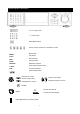
Unit Description of Front Panel 16 / 9 / 4 split screen 1 ~ 16 full screen Water Mark function Freezer / Zoom / Sequence / Information / Audio Menu button MENU : Play button PLAY : Record button REC : Key lock button LOCK : Data back up button BACKUP : Time search playback button T-SRH : Function exit button ESC : Value change button Direction UP / Down, Direction Left / Right Record and play stop, Playback forward or reverse. Playback pause / steps.
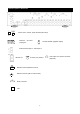
Unit Description of Rear Panel Power cord in 12V/5A, power switcher (ON / OFF) Camera 1 ~ 16 in and 75 Ohm ON/OFF (high/low adjust) looping out Audio channel input x 1 and output x 1 VGA Monitor out S-Video (Y/C) monitor RS-485 control keyboard connector RS-232 connector (ISP. For RD control) Alarm connector LAN 6 VGA output. PC monitor connector.
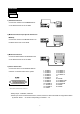
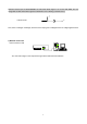
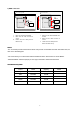
Installation Procedure 1) Camera Connection DC LEVEL Connect the camera to the CAMERA INPUT V.P CH1 CH2 CH3 VIDEO CH4 DC MONITOR on the Rear Panel of the 16 CH DVR. CH1 CH2 CH3 CH4 VIDEO LENS AC24V/DC12 Rear part of CAMERA 2) Monitor Connection (Composite Connection Method) Connect the monitor to the MONITOR OUT on CH1 CH2 CH3 CH4 CH1 CH2 CH3 CH4 MONITOR the Rear Panel of the 16 CH DVR.
NOTICE: Sensor input is RECOGNIZED as LOW when alarm signal is on a level with GND, and it is recognized as HIGH when alarm signal is FLOATING or 5V. Following is internal circuit. 5 V Internal Circuit D1 Thus, there is a danger of damage, when the sensor input goes to a Negative level or voltage higher than 5V. 5) Network Connection DVR connects to LAN ETHERNET rks TERATRAY CONNECTION ◆To view video image on the computer through internet with DVR view software.
5) HDD connection 1 How to connect single HDD 2 I/O BOARD How to connect 2 HDD I/O BOARD 1 2 1 1 MASTER tie 2 2 MAIN BOARD HDD1 3 MASTER MAIN BOARD 3 HDD SLAVE HDD2 3 Set the drive jumpers as specified by hard disk drive manufacturer. 1. Make sure the HDD is MASTER. 2. Make sure the cable connector is 1. correct. 3. Set the drive jumpers as specified by hard disk drive manufacturer. 2. Please check the HDD panel for Master set up. Make sure the HDD is MASTER and SLAVE.
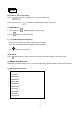
Picture Full screen or split screen display Press button, to display 16 / 9 / 4 quarterly split screen. Press numeric buttons to display the desired camera image in full screen. 1.) FREEZE Mode 1. In live mode press 2. Press (FREEZE) button to freeze image. again to cancel freeze mode. 2.) Zoom Mode(Display Enlargement.) Go to full screen mode with numeric buttons at live or playback mode, then press ZOOM button to display screen Enlargement. Use button to move position. 3.
6.) BACKUP. Image backup mode.(Image back up must be done on playback mode only.) Locate the playback point of which you want. Press BACKUP, the BACKUP CAUTION window pop-up. Press ENTER to begin data back up. Capacity of USB device is not limit. On playback mode, presses BACKUP: Lower-Right corner of the screen: ** BACKUP CAUTION ** THE ORIGINAL BACKUP FILE WILL BE KILLED. PRESS [ENTER] TO BACKUP. PRESS [BACKUP] TO CANCEL.
8.) AUDIO function )))) )))) xxxxxxxxx Audio playback: AUD (Audio), )))))))displays on the Upper-left of screen. At that time, audio will playback. Press it again to turn it off. Notice Audio playback only on normal( x 1 ) playback.
Playback 1. Playback Mode 1) Press PLAY button to begin playback. (System playback the images backward) 2. T-SRH button MAIN PLAY PAGE 1) T-SRH: Playback by time search. Press T-SRH button to active playback function. 1.MASTER TIME LIST 2.SLAVE TIME LIST 3.MASTER EVENT LIST Press direction button 4.SLAVE EVENT LIST UP/DOWN to choose 5.GOTO DATE: 2004/12/31 items. 6.GOTO TIME: 12:12 7.
2) EVENT LIST (Alarm List): Event source- Video loss / Alarm trigger / Motion / Record EVENT LIST NO Y / M / D H : M CH EVENT 10 items display on each page / Total 5000 items display for 500 pages. When event list is out of compass, the total items are less then 5000. NO Y / M / D H : M CH EVENT >Event happens time and list. CH: Event Channel Display. >1 CH ~ 16 CH Event type. >Includes Motion / Alarm / V-Loss / Record Press direction button UP/DOWN to choose items.
Function Setup LOGIN 1) Press MENU button to enter into menu. You could do the system function setup in MENU. 2) Password enter window pop-up: CHECK PASSWORD MENU PASSWORD (*****) Default password (Account-Admin) : 44444 Default password (Account-User) : 11111 3) Press numeric (1 ~ 10 )button or remote controller ( 1 ~ 10 )to choose password. 4) Remote controller function buttons are same as DVR panel function buttons.
Basic Operation Press MENU button to enter MAIN SETUP PAGE. MAIN SETUP PAGE 1. HDD INFORMATION 2. DATE-TIME SETUP 3. DISPLAY SETUP 4. CAMERA SETUP 5. BUZZER SETUP 6. RELAY SETUP 7. SYSTEM SETUP 8. ADVANCED SETUP MENU, ESC: EXIT, ENTER: RUN 1) Use direction button up/down 2) Press button to select setup item. button to enter into sub-menu function setup. 3) Press sub-menu item with direction button up/down or left/right button.
1. HDD INFORMATION MAIN SETUP PAGE 1. HDD INFORMATION POSITION SIZE USED BRAND 2. DATE-TIME SETUP MASTER 3. DISPLAY SETUP LAST TIME 4. CAMERA SETUP SLAVE 5. BUZZER SETUP LAST TIME 6. RELAY SETUP 7. SYSTEM SETUP MENU, ESC: EXIT, 8. ADVANCED SETUP MENU, ESC: EXIT, ENTER: RUN - 2 hard disk information display. Information display: POSITION SIZE USED BRAND >POSITON: Master / Slave >SIZE: Hard Disk capacity. xxGB. Maximum display is 999MB >USED: 00 ~ 100 %. Hard disk overwrites 100 ~ 199 %.
2. DATE-TIME SETUP MAIN SETUP PAGE 1. HDD INFORMATION DATE-TIME SETUP PAGE 2. DATE-TIME SETUP 1. DATE 2000 / 00 / 00 3. DISPLAY SETUP 2. TIME 4. CAMERA SETUP 3. FORMAT 5. BUZZER SETUP 3. DISPLAY AT xx LINE(S) 6. RELAY SETUP 7. SYSTEM SETUP MENU, ESC:EXIT, :MODIFY 8. ADVANCED SETUP MENU, ESC: EXIT, ENTER: RUN 1. DATE 2. TIME: > Use direction button up/down choose position, values change button to change date and time values. 3.
3. DISPLAY SETUP MAIN SETUP PAGE 1. HDD INFORMATION DISPLAY SETUP PAGE 2. DATE-TIME SETUP 1. DATE-TIME ON 3. DISPLAY SETUP 2. CAMERA TITLE ON 4. CAMERA SETUP 3. PB DATE-TIME ON 5. BUZZER SETUP 4. PB CAMERA TITLE ON 6. RELAY SETUP 5. DVR STATUS ON 7. SYSTEM SETUP 6. BORDER COLOR WHITE MENU, ESC:EXIT, :MODIFY 8. ADVANCED SETUP MENU, ESC: EXIT, ENTER: RUN 1. DATE-TIME: Date and Time caption display mode on or off setup. >ON / OFF 2.
4. CAMERA SETUP MAIN SETUP PAGE CAMERA SETUP PAGE 1. HDD INFORMATION 1. COLOR SETUP 2. DATE-TIME SETUP 3. DISPLAY SETUP 4. CAMERA SETUP 5. BUZZER SETUP 6. RELAY SETUP 7. SYSTEM SETUP 2. TITLE SETUP 3. SCREEN POSITION SETUP 4. V-LOSS DISPLAY SETUP 5. VIDEO MASK SETUP MENU, ESC: EXIT, ENTER: RUN 8. ADVANCED SETUP MENU, ESC: EXIT, ENTER: RUN COLOR SETUP PAGE (1.) COLOR SETUP ** CHANNEL NUMBER 01 1. BRIGHTNESS 00 CAMERA SETUP 2. CONTRAST 1. COLOR SETUP 2. TITLE SETUP 3.
(2.) TITLE SETUP: Input TITLE of each camera. 9 characters can be input. TITLE SETUP PAGE CAMERA SETUP 1. COLOR SETUP 2. TITLE SETUP 3. SCREEN POSITION SETUP 4. V-LOSS DISPLAY SETUP 5.
(3.) SCREEN POSITION SETUP **** SCREEN POSITION**** UP CAMERA SETUP 1. COLOR SETUP LEFT RIGHT 2. TITLE SETUP 3. SCREEN POSITION SETUP DOWN 4. V-LOSS DISPLAY SETUP ENTER : DEFAULT 5. VIDEO MASK SETUP ESC : QUIT 1. Press direction buttons up/down/left/right to move screen position. 2. Press ENTER button for default. 3. Press ESC button to quit.
(4.) V-LOSS DISPLAY SETUP VLOSS SETUP PAGE **V-LOSS FUNCTION: CAMERA SETUP CH 01 : ON CH 09 : ON 1. COLOR SETUP CH 02 : ON CH 10 : ON 2. TITLE SETUP CH 03 : ON CH 11 : ON 3. SCREEN POSITION SETUP CH 04 : ON CH 12 : ON 4. V-LOSS DISPLAY SETUP CH 05 : ON CH 13 : ON 5.
(5.) VIDEO MASK SETUP VIDEO MASK SETUP PAGE **VIDEO MASK FUNCTION: CAMERA SETUP 1. COLOR SETUP 2. TITLE SETUP 3. SCREEN POSITION SETUP 4. V-LOSS DISPLAY SETUP 5.
5. BUZZER SETUP MAIN SETUP PAGE BUZZER SETUP PAGE 1. HDD INFORMATION **BUZZER FUNCTION 2. DATE-TIME SETUP BUTTON BUZZER ON 3. DISPLAY SETUP ALARM BUZZER ON 4. CAMERA SETUP MOTION BUZZER ON 5. BUZZER SETUP V-LOSS BUZZER ON 6. RELAY SETUP HDD-FULL BUZZER ON 7. SYSTEM SETUP CRASH ON BUZZER ON 8. ADVANCED SETUP MENU, ESC: EXIT: MENU, ESC: EXIT, ENTER: RUN **BUZZER FUNCTION: All buzzer function >ON / OFF 1. BUTTON BUZZER? > ON / OFF 2. ALARM BUZZER? > ON / OFF 3.
6. RELAY SETUP MAIN SETUP PAGE 1. HDD INFORMATION RELAY SETUP PAGE 2. DATE-TIME SETUP **RELAY FUNCTION: ON 3. DISPLAY SETUP 1. ALARM RELAY: ON 4. CAMERA SETUP 2. MOTION RELAY: ON 5. BUZZER SETUP 3. V-LOSS RELAY: ON 6. RELAY SETUP 4. HDD-FULL RELAY: ON 7. SYSTEM SETUP 5. CRASH ON 8. ADVANCED SETUP MENU, ESC: EXIT, ENTER: RUN **RELAY FUNCTION: ON 1. ALARM RELAY: ON 2. MOTION RELAY: ON 3. VLOSS RELAY: ON 4. HDD FULL RELAY: ON (Relay on if hard disk record only once.) 5.
7. SYSTEM SETUP MAIN SETUP PAGE SYSTEM SETUP 1. HDD INFORMATION 1. DWELL INTERVAL 2. DATE-TIME SETUP 2. LANGUAGE 3. DISPLAY SETUP 3. VIDEO INPUT 4. CAMERA SETUP 4. RS-485 ID 5. BUZZER SETUP 5. RS-485 PROTOCOL 6. RELAY SETUP 6. RS-485 BAUD RATE 7. SYSTEM SETUP UPTIME: xx HRS MENU, ESC: EXIT: 8. ADVANCED SETUP : MODIFY MENU, ESC: EXIT, ENTER: RUN SYSTEM SETUP 1. DWELL INTERVAL: - 0 ~ 999SEC 2.
8. ADVANCED SETUP MAIN SETUP PAGE ADVANCED SETUP PAGE 1. HDD INFORMATION 1. ALARM 2. DATE-TIME SETUP 3. DISPLAY SETUP 4. CAMERA SETUP 5. BUZZER SETUP 6. RELAY SETUP 7. SYSTEM SETUP SETUP 2. MOTION SETUP 3. RECORD SETUP 4. PASSWORD SETUP 5. NETWORK SETUP 6. HDD FORMAT 7. FACTORY DEFAULT 8. ADVANCED SETUP 8. SOFTWARE UPDATE MENU, ESC: EXIT, ENTER: RUN ADVANCED SETUP PAGE 1. ALARM SETUP 2. MOTION SETUP 3. RECORD SETUP 4. PASSWORD SETUP 5. NETWORK SETUP 6. HDD FORMAT 7.
2. MOTION SETUP MOTION SETUP PAGE ADVANCED SETUP PAGE **MOTION FUNCTION ON 1. ALARM SETUP **MOTION DURATION 2. MOTION SETUP **CHANNEL NUMBER 3. RECORD SETUP 1. SENSITIVITY 4. PASSWORD SETUP 2. VELOCITY 5. NETWORK SETUP 3. ACTIVATION 6. HDD FORMAT 4. RELAY 7. FACTORY DEFAULT 5. MOTION AREA SETUP 8. SOFTWARE UPDATE MENU, ESC: EXIT: : MODIFY MOTION SETUP **MOTION FUNCTION (For all channel) -ON / OFF **MOTION DURATION -0 ~ 999 **CHANNEL NUMBER -CH 01 ~ 16 1.
> MOTION AREA SETUP < All area detect with factory default. Press ENTER button to change mode and then increase or reduce. For example: Clear lattices Press value change button to reduce. Add lattices Press value change button to reduce. Icon: Press to increase all area, press to reduce all area. Icon: Press Up / Down / Left / Right direction key to move, press to increase lattices; press Icon: + Press Up / Down / Left / Right direction key to move and increase area.
3. RECORD SETUP ADVANCED SETUP PAGE RECORD SETUP 1. ALARM 1. HDD FULL SETUP 2. MOTION SETUP 2. RECORD SPEED 3. RECORD SETUP 3. RECORD MODE 4. PASSWORD SETUP 4. RECORD AUDIO 5. NETWORK SETUP 5. QUALITY 6. HDD FORMAT 6. SCHEDULE SETUP 7. FACTORY DEFAULT 7. CHANNEL SETUP 8.
2) RECORD SPEED: Record FPS setup -1/30(1/30), 1/15(1/15), 1/10(1/10), 1/5 (1/5), 1/3 (1/3), 1/2 (1/2), 1(1), 2(2), 3(3.13), 5(5), 10 (8.33), 15(12.5), 30(25), 60(50), 120(100). 3) RECORD MODE: Record mode setup. -ALWAYS / SCHEDULE / EVENT / EVENT ON SCHEDULE / EVENT + SCHEDULE 4) RECORD AUDIO: Audio record setup -ON / OFF. (Suggest not fewer than 5 fps.) 5) QUALITY: Record image quality setup - SUPER / HIGH / FINE / NORMAL / LOW 6) SCHEDULE SETUP Press direction buttons up/down to choose item.
>SCHEDULE SETUP< RECORD SETUP 1. HDD FULL Press direction buttons up/down to 2. RECORD SPEED SCHEDULE items. 3. RECORD MODE 4. RECORD AUDIO Press values change button to change values. 5. QUALITY 6. SCHEDULE SETUP Factory default is everyday all schedules time on 7. CHANNEL SETUP recording. SCHEDULE SETUP CURSOR STEP 30MIN / 6MIN SUN MON TUE WED THU FRI SAT Press direction buttons up/down/left/right to see date and time difference.
30MIN SCHEDULE SETUP CURSOR STEP SUN 00:00 01:00 02:00 03:00 04:00 05:00 06:00 07:00 08:00 09:00 10:00 11:00 12:00 13:00 14:00 15:00 16:00 17:00 18:00 19:00 20:00 21:00 22:00 23:00 00:30 01:30 02:30 03:30 04:30 05:30 06:30 07:30 08:30 09:30 10:30 11:30 12:30 13:30 14:30 15:30 16:30 17:30 18:30 19:30 20:30 21:30 22:30 23:30 MON 00:00 01:00 02:00 03:00 04:00 05:00 06:00 07:00 08:00 09:00 10:00 11:00 12:00 13:00 14:00 15:00 16:00 17:00 18:00 19:00 20:00 21:00 22:00 23:00 00:30 01:30 02:30 03:30 04:30 05:3
7. RECORD CHANNEL SETUP PAGE RECORD CHANNEL SETUP PAGE RECORD SETUP 1. HDD FULL 2. RECORD SPEED 3. RECORD MODE 4. RECORD AUDIO 5. QUALITY 6. SCHEDULE SETUP 7.
4. PASSWORD SETUP ADVANCED SETUP PAGE 1. ALARM SETUP 2. MOTION SETUP PASSWORD SETUP PAGE 3. RECORD SETUP 1. LEVEL:( ) 4. PASSWORD SETUP 2. ADMIN:( ) 5. NETWORK SETUP 3. USER :( ) 6. HDD FORMAT 7. FACTORY DEFAULT 8. SOFTWARE UPDATE 1) Press direction buttons up/down/left/right to LEVEL (Log In level ID type setup) Choose items position. >NONE / ADMIN / USER -ADMIN Press values change button to change values. -USER -NONE, user does not need to insert password before enter in MENU.
5. NETWORK SETUP ADVANCED SETUP PAGE TCP-IP SETUP PAGE 1. ALARM 1. SPEED: SETUP 2. MOTION SETUP 2. IP TYPE : OFF 3. RECORD SETUP 3. IP ADDR: xxx.xxx.xxx.xxx 4. PASSWORD SETUP 4. GATEWAY: xxx.xxx.xxx.xxx 5. NETWORK SETUP 5. NETMASK: xxx.xxx.xxx.xxx 6. HDD FORMAT 6. D.N.S 1: xxx.xxx.xxx.xxx 7. FACTORY DEFAULT 7. D.N.S 2: xxx.xxx.xxx.xxx 8. SOFTWARE UPDATE MAC ADDR: xx.xx.xx.xx.xx.xx 1. SPEED : >512K / 512K / 256K / 128K / 64K 2.
6. HDD FORMAT ADVANCED SETUP PAGE 1. ALARM Press direction buttons up/down to SETUP HDD FORMAT items position. 2. MOTION SETUP Press ENTER to format all HDD. 3. RECORD SETUP 4. PASSWORD SETUP Caution: User can format HDD only when 5. NETWORK SETUP all HDD stop record or playback. 6. HDD FORMAT 7. FACTORY DEFAULT 8. SOFTWARE UPDATE Æ HDD FORMAT CAUTION!! : ** HDD FORMAT CAUTION!!** ALL DATA IN HDD WILL BE Press ENTER button to format hard disk. DESTROYED!! PRESS [ENTER] TO FORMAT.
7. FACTORY DEFAULT ADVANCED SETUP PAGE 1. ALARM SETUP 2. MOTION SETUP Press direction buttons up/down to 3. RECORD SETUP FACTORY DEFAULT items position. 4. PASSWORD SETUP Press ENTER to restore. 5. NETWORK SETUP 6. HDD FORMAT 7. FACTORY DEFAULT 8. SOFTWARE UPDATE ** CAUTION!! ** ALL SETUP VALUE WILL BE CLEAR, Press ENTER button to restore. AND RESTORE FACTORY DEFAULT!! PRESS [ENTER] TO RESTORE. Press ESC button to cancel. PRESS [ESC] TO CANCEL. 8. SOFTWARE UPDATE ADVANCED SETUP PAGE 1.
USB Data Read and Networking 1. Windows 2000 / XP 2. Resolution 1024 x 768. 3. RAM up to 128 MB 4. Double click SETUP.EXE of CD, and then start to install. 5. Browse install path and then click Next.
6. Name chooses and then click Next. 6. Click create a desktop icon or not, and then click Next.
7. Click INSTALL to start install. 8. Click Launch Netviewer 163A and click Finish to done.
9. Click Setting. Name: Name the IP address position.(Each name and IP saves every different input) IP Addr: Input DVR IP address. AVI codec: Not support currently. (Next version update.) Video: Fullsize, Halfsize: Not support currently. (Next version update.) NTSC, PAL. Frame/Sec: Not support currently. (Next version update.) Click OK to confirm. On Live / PlayBack 時, click DVR to save action pictures, *.DVR file. It needs this software to play. Browser, Local record path could change.
10. Click Login, depends on limits of authority. Factory ID is guest login. Input admin if you are a administer. Must input on little character. Password, admin : 123456, guest : 123456. Password displays when log in, user just needs to input ID. Guest log in, no PlayBack function authority. Click OK, after about 5 seconds, admin login!! Message popup. And then click Connect to start.
11. Click Connect, after about 2 ~ 3 seconds to start connect LAN or WAN. Click Disconnect to stop. If the NETWORK is connecting success, the blue light would keep glisten Else, blue is always on light or not display, the connecting is failed. Click live / PlayBack / BackPlay mode. Live: DVR live watching. PlayBack: Change to playback mode. After 2 ~3 seconds to change.
PLAY: Click RUN around 2 ~ 30 seconds to start play first record. If over 30 seconds, cannot find any file or network disconnect, Time out message popup. Please try again play or connect again. Click STOP to end playback. TIME LIST: Click RUN, time lists popup. On the item, double click it to start play, around 2 ~ 30 to start play first record. If over 30 seconds, cannot find any file or network disconnect, Time out message popup. Please try again play or connect again. Click STOP to end playback.
12. BackupPlay: - Click Open to choose file path.
Click Play to start backup data play. Click Stop to end. Click Pause to temporary stop playback. Click Resume to restart. Choose camera, click mouse right button. Camera 1 ~ 16 switches or reset all. Click Save “CamNo xx image . / save image all to save current image. Save path is C:\DVR.
Record Time Table: 80GB HD Record Quality: Low. KB Range: Lowest: 13, Highest: 20. Average: 17. REC FPS 120 60 30 15 10 REC Hour 21.7 21.7 43.5 87.1 130.7 REC FPS 5 3 2 1 1/2 REC Hour 261.4 435.7 653.5 1307.1 2614.3 REC FPS 1/3 1/5 1/10 1/15 1/30 REC Hour 4357.2 6535.9 13071.8 21786.4 43572.8 Record Quality: Normal. KB Range: Lowest: 14, Highest: 25. Average: 20. REC FPS 120 60 30 15 10 REC Hour 18.5 18.5 37 74 111.1 REC FPS 5 3 2 1 1/2 REC Hour 222.
VGA Description (Optional) Accessories: 1. 20 PIN Male to Female D-SUB pin cable X 1 2. VGA PCB bracket X1 3. Screws X4 (Only fit on product serials Z7-00-VGA0-00) 1. VGA board introduction. VGA connector Socket Resolution and NTSC/PAL switcher 3.
Additional Hard Disk x 2 can be installed on DVR base. Both are 2-iron slices immobile type. 2 Iron slices are in the accessories box, please tell supplier if slices are not exist 2-iron slices immobile type: Slices immobile type: 4 screws hole on each slice. 2 for DVR base fixed. Another 2 for hard disk fixed. Hard disk install.: Locking hard disk screws, then locking DVR base screws to fixed on.