4 CH Digital Video Recorder User’s Manual Please read this instructions thoroughly before operation and keep the manual in a safe place for further reference. 771-A V 1.
WARNING All the safety and operating instructions should be read before operation. The improper operation may cause permanent damage. • This adaptor is only for this machine. Do not use it for other electronic products or it may damage other products. • Please lift and place this equipment gently. • Do not expose this equipment from direct sunlight and keep it away from sources of intense heat. • Do not use this equipment near water or in contact with water. • Avoid dusty or humid place.
TABLE OF CONTENTS What do you get ? • FEATURES ---------------------------------------------------------------------------------------- 3 • PACKAGE CONTENT -------------------------------------------------------------------------- 3 Before Operation • INSTALLATION GUIDE ------------------------------------------------------------------------ 4 • FRONT PANEL ----------------------------------------------------------------------------------- 5 • REAR PANEL -----------------------------------------------
What do you get ? FEATURES DVR Features • Wavelet compression format replaces Time-Lapse VCR + Multiplexer / Quad • On Screen Display and Remote Control via Video Server & PC • Picture-in-picture (PIP) and Picture-on-Picture (POP) function in live • Alarm input & output function • Video loss detected on each channel • Multiplexer & Quad recording mode switching • Recording rate up to full size 30 fields/sec. or Quad size 240 fields/sec.
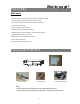
INSTALLATION GUIDE Before Operation 1. Connect cameras and monitor to the DVR. 2. Shown below is an example of connecting the DVR to your existing Observation System. 3. Install HDD (The compatible HDD Brands are listed in the following table.) Please refer to page 19. Appendix #1 for installation instructions. *The HDD must be installed before turning on the DVR. If HDD is not installed, the DVR would function as a 4 CH multiplexer.
FRONT PANEL LED LIGHT The LED Light is ON under following condition. •HDD : HDD is reading or recording. •HDD Full : HDD is full •ALARM : To turn off the ALARM LED light, please refer to page.13 and set the ALARM mode as OFF. •TIMER : When Timer is Enabled •PLAY : Playing mode •REC : Recording mode MENU Press MENU to enter main menu. ENTER Press ENTER for confirmation SEARCH Press SEARCH for searching recorded video. / POP Press “ ” button for Picture on Picture screen.
FF / ► •FF : Play video fast forward. (Press FF button again to adjust speed from 1, 2, 4, 8, 16, 32 times) • ► : Under setup mode, it works as Right button. REW / ◄ •REW : Play video fast backward. (Press REW button again to adjust speed as 1, 2, 4, 8, 16, 32 times) • ◄ : Under setup mode, it works as Left button. STOP / ▼ •STOP : Under DVR Record / Play mode, it can stop the action. • ▼ : Under setup mode, it works as Down button. •Pause : Under DVR play mode, it can pause the action.
REAR PANEL IN 1 2 OUT 3 4 MAIN CALL DC 19V EXTERNAL I/O 1 2 4 5 6 1. EXTERNAL I/O •Controlled remotely by an external device or control system like Video Web Server. •Alarm input, external I / O expansion. 2. VIDEO INPUT (1-4) Connect to video source, such as camera. 3. MAIN Connect to Main monitor. 4. CALL Connect to CALL monitor. Show the Switch Display. When alarm is triggered, the call monitor will show the triggered channel according to the system setting. 5.
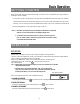
Basic Operation GETTING STARTED Before using the DVR, please have a HDD installed ready, or it will function as 4 CH multiplexer (refer to Appendix #1 for installation or removal of a HDD). 1. Connect the AC power cord and plug into an electrical outlet. The POWER LED will turn into orange color, and other red LED indicators will turn ON. It takes approximately 5 to 15 seconds to boot the system with the message : “ HDD Detecting ”.
PLAY BACK Press “ PLAY ” button, the DVR will show the last recording. 1. FAST FORWARD (F.F.) & FAST REWIND (F.R.) You can increase the speed of Fast Forward and Rewind on the DVR. In the Play mode, press “ ► ” once to get 2X speed forward and press twice to get 4X speed,… and the maximum speed can reach 32X. Press “◄ ” once to get 1X speed rewind and press twice to get 2X speed, … and the maximum speed can reach 32X. 2. SLOW FORWARD (S.F.) & SLOW REWIND (S.R.
Detailed Menu Setup MAIN MENU There are 11 options available in the Main Menu: (MENU) TIMER CAMERA RECORD ALARM DWELL PIP DISPLAY REMOTE USER SYSTEM EVENT TIMER ---------- Program Timer Recording CAMERA ------- Camera Setup RECORD ------- Recording Mode Setup ALARM --------- Alarm Setup DWELL --------- Dwell time Setup PIP --------------- Picture in Picture Setup DISPLAY ------- Display Mode Setup REMOTE ------- Remote Control Setup USER ----------- User Password Setup SYSTEM ------- System Setup EVENT -
6. MESSAGE LATCH To select whether the DVR messages will disappear after 10 seconds or remain on screen. NO is the default setting which the messages will disappear after 10 sec. NOTE : Video loss, and Alarm messages will be shown the same as Alarm Duration time. 7. DATE DISPLAY To set the date Y/M/D, M/D/Y, D/M/Y and OFF on monitor or not. 8. DATE To set the date on the DVR. 9.
(TIMER) DAY START END IPS DAILY 01:00 22:00 30 OFF 00:00 00:00 30 OFF 00:00 00:00 30 OFF 00:00 00:00 30 OFF 00:00 00:00 30 OFF 00:00 00:00 30 OFF 00:00 00:00 30 OFF 00:00 00:00 30 TIMER ENABLE : YES 2. START Set the time to start the recording. 3. END Set the time to end the recording. 4. IPS (IMAGES PER SECOND) NTSC-30、15、8、4、2、1 PAL-25、12、6、3、2、1 QLT MODE BEST Q-FR BEST Q-FI BEST Q-FI BEST Q-FR BEST Q-FR BEST Q-FR BEST MUX BEST Q-FI 5.
3. REC (RECORD) Set up which channel you want to record. ON : when alarm input is triggered, DVR will record alarming channel more frequently. For example : when CH01 is triggered, the record method will become 1-2-1-3-1-4…. OFF : DVR will not record. 4. BR (BRIGHTNESS) Adjust the brightness of each channel. The level is from 0 to 63. 5. CT (CONTRAST) Adjust the contrast of each channel. The level is from 0 to 63. 6. CL (COLOR) Adjust the color of each channel. The level is from 0 to 63. 7.
3. REC IPS Select the images per second of recording during an ALARM. The options are as following: NTSC-30、15、8、4、2、1 PAL-25、12、6、3、2、1 (ALARM) ALARM ENABLE YES 4. QUALITY ALARM DURATION 15 MIN There are four recording quality settings during an ALARM : RECORD IPS 30 BASIC, BEST, HIGH, NORMAL. QUALITY NORMAL 5. RECORD MODE RECORD MODE QUAD-FRAME There are three recording settings : QUAD-FRAME, QUAD-FIELD, MULTIPLEX. DWELL 1.
3. LOSS SCREEN Retain the last picture or select the LOSS SCREEN color. The options are GREEN, BLACK, BLUE and RETAIN. 4. TIME POSITION To set the OSD POSITION shown on monitor. The options are NORMAL or CENTER. (DISPLAY) TITLE DISPLAY OSD COLOR LOSS SCREEN TIME POSITION YES YELLOW GREEN NORMAL REMOTE 1. REMOTE MODE Set the remote mode for connection with computer via RS-232 or RS-485. (Please refer to page. 20& 21 for RS-232& RS-485 Remote Control). 2.
EVENT A single page can display 16 recorded events. Press “◄ ” or “► ” to change the pages or press “▲ ” + “▼ ” to CLEAR the EVENT record.
KEY LOCK For advanced security, you can “Lock” the buttons on your DVR. Key-Lock prevents other people from using the system. Press ENTER and MENU at the same time to enable Key Lock. Press ENTER and MENU at the same time and key in password (Default : 0000), then press “ENTER“ to disable Key Lock. NOTE: To switch to different USER, press “ENTER” + “MENU” buttons to “KEY LOCK” and then enter the different user’s password to UNLOCK. RS-232 REMOTE PROTOCOL You can use the PC keyboard to simulate DVR keypad.
SPECIFICATIONS NTSC/EIA or PAL/CCIR Video format Hard disk storage IDE type, UDMA 66, supported 250 GB HDD Manual / Alarm / Timer Record mode Camera Input Signal Composite video signal 1 Vp-p 75Ω BNC, 4 channels Main Monitor Output Composite video signal 1 Vp-p 75Ω BNC Call Monitor Output Composite video signal 1 Vp-p 75Ω BNC Video Loss Detection Refresh Rate Recording Rate Yes Up to 240 fields/sec. for NTSC / 200 fields/sec. for PAL Multiplex: Up to 30 fields/sec. for NTSC / 25 fields/sec.
APPENDIX #1 – INSTALL THE HDD Follow these steps carefully in order to ensure correct installation. HDD Bracket HDD Power Cable Fig.1 HDD Power Cable Fig.2 Fig.3 Step 1 Remove the lid and unscrew the screws from HDD bracket module . Step 2 Insert the HDD into the HDD bracket and screw the four screws. The bottom side is power side as chart shows (refer to the Fig 1). Step 3 Connect the HDD power cable to the HDD (refer to the Fig. 2).
APPENDIX #3 – PIN CONFIGURATIONS 15 pin com port • • DVR • • 9 pin com port • • DVR DQR • • 20
PIN 1. RS232-TX : RS-232 DVR can be controlled remotely by an external device or control system, such as a control keyboard, using RS232 serial communications signals. PIN 2. RS232-RX : RS-232 DVR can be controlled remotely by an external device or control system, such as a control keyboard, using RS232 serial communications signals. PIN 3, 4, 5, 6 ALARM INPUT To connect wire from ALARM INPUT (PIN 3, 4, 5, 6) to GND ( PIN 9 ) connector, DVR will start recording and buzzer will be on.
APPENDIX #4 – RECORDING SPEED The Record Time is different based on Recording Speed, Recording Quality and Recording Mode. Please refer to following table. The HDD capability is 250GB.
APPENDIX #5 – NETWORK APPLICATION Video Web Server Features • Compatible with most of CCTV Products; empower any video output device watching and controlling on the Internet or LAN • Auto Network Reconnection (ANR) • Upgrade firmware & AP from FTP site via Video Web Server • Watch dog function supported • Support Dynamic IP address • 4 alarm inputs supported • Duplex function, record and playback simultaneously at client site • Auto e-mail warning system which will remind you if external alarm happened • In