Installation & Safeguards INSTALLATION & SAFEGUARDS All the safety and operating instructions should be read before the unit is operated. Environment Condition for Installation To prevent electric shock or other hazard, do not expose units to rain, moisture, or dust. This unit should be located in an area with low humidity and a minimum of dust.. Place this unit in a well-ventilated place and do not place heat-generating objects on this unit.
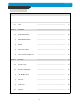
Contents Contents CHAP. 1 Features & Package Contents ---------------------------------------------------------------- 4 1-1. Features ---------------------------------------------------------------- 4 1-2. Package Contents ---------------------------------------------------------------- 5 Function of Each Button ---------------------------------------------------------------- 6 2-1. Front ---------------------------------------------------------------- 6 2-2.
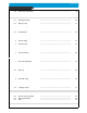
Contents 4-9. PTZ Camera Operation ---------------------------------------------------------------- 19 Data Back-Up ---------------------------------------------------------------- 19 Set Up ---------------------------------------------------------------- 20 5-1. Entering the Menu ---------------------------------------------------------------- 20 5-2.
CHAP. 1 Features & Package Contents CHAP. 1 Features & Package Contents 1-1.
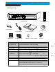
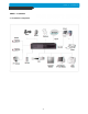
CHAP. 1 Features & Package Contents 1-2. Package Contents 1. DVR Main Unit 2. Remote Controller 3. Power Cable 6. Software CD 4. Power Adapter 7. Rubber Pad 8. HDD absorber 5. User’s Manual 9. Battery for remote controller Package Contents 10. Bolts Description 1. DVR Main Unit STAND-ALONE DIGITAL VIDEO RECORDER 2. Remote Controller DVR control 3. Power Cable AC power supply to adapters for 12 V DC power 4. Power Adapter 12 V DC power supply 5. User’s Manual User’s Manual 6.
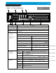
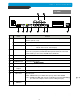
CHAP. 2 Function of Each Button CHAP. 2 Function of Each Button 2-1 FRONT Name Function ① LED Lamps Shows status of operation ② USB Device Firmware upgrade by connecting PC with latest firmware to USB port ③ IR IR receiver ④ Camera selection & PTZ camera control 1. Pressing this button will display a full screen image of that camera ⑤ Record / Playback 2.
CHAP. 2 Function of Each Button Name ⑦ LIVE View Control Function PTZ ZOOM Zooming an image FRZ Freezing an Image MODE ⑧ Jog Shuttle Control On/Off for PAN/TILT/ZOOM control mode Press this button first to control PTZ camera connected to DVR unit via RS-485 Switch to split display MODE button changes screen-division from (to) full screen to (from) 4-split screen. PIP Display in PIP (Picture in Picture) mode SEQ Auto camera image sequencing in full screen mode K.LOCK Lock the key function.
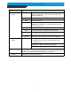
CHAP. 2 Function of Each Button 2-2. REAR Name 1 RS 485 Function Connection with PTZ Camera or other external device using RS 485 interface (Pin No.1 & 2) RELAY Output Relay out terminal (Pin No.3, 4 and 5) SENSOR Input Sensor input terminal(Pin No.6 : Ground, Pin No.
CHAP. 3 Installation CHAP.3 Installation 3-1.
CHAP. 3 Installation 3-2. Detailed Installation 1) Rack mount 1. Remove 4 bolts on each side cap to install rack mount. 2. Attach rack mount bracket to DVR. 3. Attach DVR with rack mount bracket to 19” rack. 2) HDD 1. Connect Main Board and HDD1 using IDE cable and HDD power cable. 2. The jumper setting of HDD1 should be on Master if you install only one HDD. 3. The jumper setting of HDD1 should be on Master and HDD2 should be on Slave if you install two HDDs.(Refer to the above figure) 4.
CHAP. 3 Installation 3) Camera Connect cameras to the camera input on rear panel of DVR marked CAMERA IN. 4) Monitor CA MERA IN CH2 CH1 CH3 MONITOR CH4 VCR L OOP Connect the video output marked MONITOR to Video-In of Main monitor. 5) Power CA MERA IN CH1 CH2 CH3 L OOP Do not connect the Main power and Sub power at the same time if this jumper has not been removed.
CHAP. 3 Installation 6) VCR, VIDEO PRINTER MONITOR CA MERA IN CH1 CH2 CH3 CH4 L OOP VCR Connect VCR or VIDEO Printer to VCR out on the rear panel of DVR. 7) Other External Device RS-232C : Control DVR through RS-232C port by using PC. RS-485 : Control external device like PTZ Camera (Pin No.1 & No.2 at Terminal Block). RELAY Output : Relay Output (Pin No.3 ~No.5 at Terminal Block). SENSOR Input : SENSOR Input (Alarm connection)(Pin No.6 ~ No.10). ETHERNET : Connection to LAN, WAN, Internet.
CHAP. 3 Installation 8) Connector Pin Assignment No Description NO Description 1 DCD Data Carrier Detect 6 DSR Data Set Ready 2 RxD Receive data 7 RTS RS232C: Rx/Tx data 3 TxD Transmit data 8 CTS RS232C: Rx/Tx data 4 DTR Data Terminal data 9 5 GND Signal Ground 9) RS-232C ASCII-code Following ASCII-Codes(Hexa-Code) are for programmers who want to control DVR unit via the RS232C Port using keyboard of PC. All ASCII-Code is 1 Byte.
CHAP. 4 Operation CHAP.4 Operation 4-1. Power connection Connect power adapter to MAIN only if you use 1 or 2 HDD under 200GB & CD writer. Connect 2 power adapters (both MAIN and SUB) if you use HDD with capacity of 200 GB or larger & CD writer. ※ DVR will not work if you connect the power adapter to SUB jack only. ※ Please refer to the Instruction for DC Power Adapter Connection included in the package for details.
CHAP 4. Operation 4-3. Factory Default Before initial configuring or operation you must first set Time/Date, followed by setting the unit to the FACTORY DEFAULT settings, lastly clearing the HDD. Please follow these steps in order. Improper operation may result if this action is not taken. 2. FACTORY DEFAULT 1.
CHAP. 4 Operation 4-5. Live View Setup 1) Full / Multiple View Switch to multi-screen display by pressing [MODE]. For full image display, just press the channel button which you want or [MODE] button again. Full screen Full screen Multi-screen [MODE] [MODE] or Channel button 2) View in Sequence Press [SEQ] button. It automatically displays full screen images in sequence.
CHAP. 4 Operation 4-6. Record Recording mode set before delivery by manufacturer (Default recording mode) is Schedule Recording. In this default recording mode, it records 24 hours/day continuously in weekday and on the weekend. Once you press the [REC] button while you see live view, the record type is changed to Emergency Record mode.
CHAP. 4 Operation 4-8. Search Press [SEARCH] button, and 3 different methods for searching recorded data are available as shown in following SEARCH window. For selecting searching method, use direction key or Jog/Shuttle. After selecting each search method, press [ENTER] button for playback. 1) SEARCH BAR Search by percentage of total recorded data. It starts from image corresponding to set % of data on the search bar. 2) TIME/DATE Search by time & date. Playback starts from the time & date selected.
CHAP. 4 Operation 4-9. PAN/TILT/ZOOM Camera Operation Press [PTZ] button first for PTZ control mode. Numeric buttons from 1 to 16 and direction buttons are assigned for each PTZ command, and user can control PTZ camera connected to DVR unit by pressing any one of those 20 buttons, one after the other, as needed, and it is just like control by separate PTZ controller.
CHAP. 5 Set Up CHAP. 5 Set Up 5-1. Entering into the Menu Enter into SYSTEM MENU by pressping [MENU] button.
CHAP. 5 Set Up 5-2. DIPLAY SETUP Setting up parameters for monitor and display on screen. Enter into SYSTEM MENU-DIPLAY SETUP. DISPLAY SETUP LIVE PLAYBACK SCREEN DISPLAY MONITOR SETUP VGA SETUP COLOR BAR TEST SELECT MENU : ▲▼, & [ENTER] 1) SCREEN DISPLAY 1 2 3 4 Setting up the screen display in LIVE mode and PLAYBACK mode. Select the sub-menu which you would like to set using direction buttons and then change ON/OFF with [ENTER] button. 1. TIME/DATE : Display time & date 2.
CHAP. 5 Set Up 5-3. CONFIGURATION Various parameters for system can be set in CONFIGURATION menu. Enter into SYSTEM MENU-CONFIGURATION and press the [ENTER] button.
CHAP. 5 Set Up 2) TIME/DATE SETUP Set time and date of DVR system which is very important for search with time and date of the event. Time and date set by manufacturer is different from local time of user, and user must set time and date exactly in first operation.
CHAP. 5 Set Up CAMERA ACTIVE SETUP MOTION CONFIGURATION CHANNEL CH STATUS LIVE REC --------------------------------------------------------------------------01 02 03 04 ACTIVE ACTIVE LOSS ACTIVE ON ON OFF ON 01 SENSITIVITY GRADE ON ON OFF OFF MOTION DISPLAY TYPE RECORD DURATION 4 OFF 05 SEC SELECT ▲▼, PRESS ◀▶ SELECT : ▲▼, CHANGE VALUE : ◀▶ (3) CAMERA ACTIVE SETUP : With direction button, move to option to be changed, and press [ENTER] button to select [ON/OFF].
CHAP. 5 Set Up INTERVAL SETUP SWICHING INTERVAL 4) INTERVAL SETUP Set the switching time interval for SEQ or PIP function.(1 sec. ~ 99 sec.) FULL SCREEN : 01 SEC PIP SCREEN : 01 SEC EVENT RECORD FULL SCREEN : set the sequencing switch time interval in live full screen. EVENT UPDATE TIME PIP SCREEN : set the sequencing switch time interval of PIP window. : 01 SEC SELECT ▲▼◀▶, & PRESS [ENTER] EVENT UPDATE TIME : Set the minimum time interval of event to be listed in EVENT LIST.
CHAP. 5 Set Up 6) BUZZER SETUP BUZZER SETUP Set parameters for buzzer (On or Off). Use direction button and [ENTER] button. KEY BEEP : buzz when button is pressed. VIDEO LOSS : buzz when video signal is lost. ALARM ACTIVE : buzz when alarm is activated. MOTION DETECT : buzz when motion is detected. ALL ON KEY BEEP ON VIDEO LOSS ON ALARM ACTIVE ON MOTION DETECT ON User can set all buzzers at On/Off at once by set ALL at ON.
CHAP. 5 Set Up 5-4. RECORD SETUP This is the most important configuration of the DVR. Enter into SYSTEM MENU-RECORD SETUP and press the [ENTER] button. 1) RECORD CONFIGURATION Use direction button to move and [-] [+] button to set value. (1) OVERWRITE : Set overwrite or stop recording when the HDD is full. (2) MULTIPLEX RECORD SETUP RECORD CONFIGURATION SCHEDULE SETUP HOLIDAY SETUP - DUPLEX : Playback & Ethernet (3) QUALITY : Sets recording picture quality.
CHAP. 5 Set Up 2) SCHEDULE SETUP Unless you selected other recording mode, DVR system records in Schedule Recording mode. In SCHEDULE REC SETUP, you set type of recording for every time interval of 2 hours in each day of the week. Schedule Recording set by manufacturer is recording continuously at its full recording speed, and it means DVR system record continuously at 60 ips in total at 720x240 resolution.
CHAP. 5 Set Up 5-5. BACK-UP User can back up the recorded data to CD using CD writer installed in DVR. For instructions, please refer to page 19. CD-R SETUP HDD [START] 2005/AUG/07 AM04:04:12 [ END ] 2005/AUG/08 PM08:12:23 CD-R [START] 2005/AUG/07 AM04:04:12 [ END ] 2005/AUG/08 PM08:12:23 [ SIZE ] 000MB BURN SELECT : SETUP BUTTON, JOG SHUTTLE System Status Messages : - CD-RW DOOR CLOSE. CHECKING CD-R : Blank CD check - INPUT BLANK CD : CD writer has no blank CD.
CHAP. 5 Set Up 2) RS-232C SETUP User can control the DVR via RS-232C port. Connect DVR to PC via RS-232C port and user can control DVR using keyboard of PC. This function is mainly for programmer who wants to control DVR as part of many devices connected to PC system. 3) PAN/TILT SETUP Set parameters for PTZ cameras connected to the DVR unit. DVR unit already includes all protocols of well-known PTZ cameras like PELCO D type PTZ cameras.
CHAP. 5 Set Up 5-7. FACTORY DEFAULT Set all system elements to the factory default value. Use the direction buttons to move and press the [ENTER] button to set. After setting the values to ON, select RUN, press [ENTER]. If the ALL setting was configured to ON, then the entire system has been set to factory default settings. This method is used to initialize the unit and is required for some operations, such as firmware upgrades, HDD installations, and prior to initial setup.
CHAP. 6 Network Setup CHAP. 6 Network Setup 6-1. DVR Network Configuration Now that you are familiar with the equipment and should be able to identify a router from a modem and a Cat5 network cable from a telephone cable, we will proceed to determine the network scenario that fits your current network. Please call your provider to identify what type of service they are providing you.
CHAP. 6 Network Setup Case A : Single Static IP w/Personal Router Phone line Or CATV Internet (ISP) Personal Router w/ switch modem PC DVR Configure the DVR as follows : 1. Set the DVR to MANUAL for the TCP/IP settings. Do not use DHCP SETUP for this application or verify that DHCP SETUP is set to MANUAL. 2. IP ADDRESS : assign it a private IP address (ex : 192.168.1.105) a. You need to assign the DVR an IP address just as you would a PC. b.
CHAP. 6 Network Setup REMOTELY : To access the DVR remotely, that is from outside your local network, follow the above directions for accessing locally, except for the IP address. For CASE A, you have received a static IP from your Internet provider. That static IP address is what you must enter into the software for connectivity to take place (NOT the IP of the DVR). Contact your provider if you have misplaced the forms stating your static IP address.
CHAP. 6 Network Setup REMOTELY : To access the DVR remotely, open the remote viewing software and click on the “Settings” button. As far as TCP/IP connectivity is concerned only 4 entries need to be made : For CASE A, you have received a static IP from your Internet provider. That static IP address is what you must enter into the software for connectivity to take place(this should be the same IP address configured in the DVR).
CHAP. 6 Network Setup Accessing the DVR using the Remote Software for CASE C LOCALLY : To access the DVR locally, that is from your local network on site from where the DVR is installed. Open the remote viewing software and click on the “Settings” button. As far as TCP/IP connectivity is concerned only 4 entries need to be made : 1. IP address : Input the IP address that you assigned the DVR. As in the above example I would input the private IP address of 192.168.1.105 2.
CHAP. 6 Network Setup 4. SUBNET MASK : 255.255.255.240 (example) a. Along with your static IP addresses you should have received your subnet mask from your Internet provider. Please use that subnet mask when configuring the DVR. If you did not receive this information contact your service provider. 5. GATEWAY : 24.106.1.193(example) a. Along with your static IP addresses you should have received your gateway or default gateway from your Internet provider. Please use that gateway when configuring the DVR.
CHAP. 6 Network Setup Configure the DVR as follows : For this application you can still use the DVR for remote access, yet you will have to verify the IP address within the DVR on a continuous basis to ensure the IP address hasn’t changed. This setup will not work with most Dynamic DSL providers. In any instance in which the DVR cannot detect an IP, please use CASE C. 1. Unplug the power from the modem. 2. Turn off the DVR. 3. After waiting 5 minutes, power on the modem followed by the DVR. 4.
CHAP. 6 Network Setup 6-2. Remote Viewer program MAIN INTERFACE 1 6 7 8 5 2 1 2 3 4 5 6 7 8 3 4 - Power switch : Press the Power switch to exit the program. Please disconnect the live feed before powering off the software - Connect button : Press the Connect button to view the live images from the DVR. These are the same images being displayed on the monitor of the DVR, with a delay depending on your internet connection at both the DVR location and from where you’re currently accessing.
CHAP. 6 Network Setup Setting Screen Name(LABEL) : This just identifies your settings. The settings are automatically saved under this label when you hit ‘OK’. IP Address : Based on your network scenario and from where you’re accessing, enter the appropriate IP address. PORT : Enter the Port Number you assigned the DVR. ID : Always enter ‘admin’ Password : This must match the password on the DVR. For simplicity, just use numbers.
CHAP. 6 Network Setup PlAYBACK INTERFACE through Remote Viewer 2 1 3 7 8 9 10 4 5 6 Function of each button in Search window. 1 2 3 4 5 6 7 8 Exit : Exit to live window. Full screen : Select a certain camera to view in full screen. Quad : To view quad mode (4 channels at the same time) Time : The recording time & date information of the pictures which is being played. Channel selection : Select each camera. Time selection : Select a time from which user want to see.
CHAP. 6 Network Setup : Play Fast backward : Move to the start of recording : Play backward(1X) : Move to the previous hour : Play Forward(1X) : Move to the afterward hour : Play Fast Forward : Move to the end of recording : Stop playback 9 : Command button. a) Save : After pressing the Stop button, you can save the currently viewed channels as an image (jpg) b) Print : After pressing the Stop button, you can print the currently viewed channels. c) EVENT : Not available.
CHAP. 6 Network Setup 10 : Calendar Use this to select the date you wish to playback. The filled in square outlines the date that is at the beginning of the hard drives. The outlined square indicates the data at the end of the hard drives. Select the date you wish to view. Verify a filled in square for that particular date. If an invalid date is selected it will default to the beginning of the hard drive(s).
CHAP. 6 Network Setup 6-3. Back-up CD Player 1 9 2 3 b e c d 4 d a f 8 5 7 6 To view the data stored on your backup CD from the DVR unit, please use this software. The functions are described below. 1. Time : Current time. 2. Status Window : Start & End of time & date, Status of operating button. When user play forward/backward, recorded time will appear. 3. Play Speed button : User can adjust play speed by pressing up/down button. (2X,4X,8X,16X,32X,64X) Delay : (1, 1/2, 1/4, 1/8, 1/16) 4.
CHAP. 6 Network Setup Image EDIT 1 Contrast a a Sharpness 2 b b Blur Brightness Save Print a Exit b c 3 1. Image edit status window : Shows record time & date, Image size, Command status. 2. Edit button : User can adjust color tone of copied images using this button.
CHAP. 6 Network Setup 6-4.
CHAP.
CHAP.
CHAP.
CHAP. 6 Network Setup Can I configure my DVMR for remote access using a Dial-Up connection? Yes, it is possible, but not recommended. With a live video feed, the bandwidth that a dial-up connection provides is very poor. In addition, you will have to install a device that allows your DVMR to connect directly to your dial-up phone line (roughly $200).
• The best picture quality in Playback(JPEG-2000) • Real time live display in all channels • 4 channel video 240(200)ips recording capability • Triplex (Playback/Recording/Ethernet) • Multi-language menu • Remote monitoring and download through network • Various N/W environments support (PPPoE) • Convenient search function with Jog-shuttle • VGA option available (Supporting TFT LCD Monitor) • USB (Device) port for firmware upgrade • Easy PTZ camera control by pre-assigned buttons • Password Protection • Rem