WARNING 1
DVR WARNING All the safety and operating instructions should be read before operation. The improper operation of this device may cause permanent damage. ‧ Please use the provided adapter (Other adapter is not suitable for this machine). ‧ Please lift and place this equipment gently. ‧ Do not expose this equipment to open sunlight. ‧ Do not use this equipment near water or in contact with water. ‧ Do not spill liquid of any kind on the equipment. ‧ Please power down the unit before unplugging.
TABLE OF CONTENTS DVR What do you get ? ‧ FEATURES ---------------------------------------------------------------------------------------- 3 ‧ PACKAGE CONTENTS ------------------------------------------------------------------------- 3 Before Operation ‧ INSTALLATION GUIDE ------------------------------------------------------------------------ 4 ‧ FRONT PANEL ----------------------------------------------------------------------------------- 5 ‧ BACK PANEL ---------------------------------------
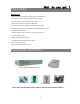
What do you get ? FEATURES DVR Features • Wavelet Compression Format replaces Time-Lapse VCR + Multiplexer • 4 Audio inputs / 2 Audio outputs (selectable 1-channel recording) • On Screen Display and RTC (Real time clock) Function • Support from 1 channel to 4 channels of video inputs • Picture-In-Picture (PIP) is available in live and DVR playback modes • Motion detection function and 4 Level video quality adjustable on each channel • Alarm Input & Output Function • Video loss detection on each channel (c
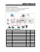
INSTALLATION GUIDE Before Operation 1. Connect cameras and monitor with the DVR. 2. Shown below is one example for connecting the DVR to your existing Observation System. 3. Install HDD (The compatible HDD Brands are listed in the following table.) Please refer to page.19 Appendix #1 for installation instructions. The HDD must be installed before turning on the DVR.
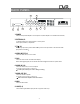
DVR FRONT PANEL 2 17 CDR-04S HDD 1 1 2 3 MENU ENTER SEARCH 3 4 5 HDD FULL TIMER ALARM 4 SLOW 16 Z0 0M 6 7 8 REW FF 14 12 13 1. REMOVABLE HDD CARTRIDGE Please refer to page 19, Appendix #1. 2. LED LIGHT The LED Light is ON under following conditions. ‧HDD Full : HDD is full ‧ALARM : If you want to turn off the ALARM LED light, please refer to page.13 and set the Camera / ALARM item as OFF. (all of the cameras should be set as OFF.
11. POWER Press Power to turn ON / OFF the DVR. 12. FF / Right ‧FF : It can play video forward at high speed, and press FF again to adjust speed from 1, 2, 4, 8, 16, 32 times. ‧Right : Under setup mode, it can work as Right button. 13. PAUSE / Up ‧Pause : Under DVR play mode, it can pause the action. ‧UP : Under setup mode, it works as Up button. 14. REW / Left ‧REW : Under DVR play mode, it can play video backward at different speeds.
DVR BACK PANEL 9 8 MAIN LOOP IN OUT RISK OF ELECTRIC SHOCK DO NOT OPEN HI POWER 1 EXTERNAL I/O 2 INPUT 75Ω 3 CALL 4 1 3 R 2 4 L 6 5 WARNING : TO REDUCE THE RISK OF ELECTRIC SHOCK, DO NOT REMOVE COVER (OR BACK). NO USER-SERVICEABLE PARTS INSIDE. REFER SERVICING TO QUALIFIED SERVICE PERSONNEL. 7 1. POWER Please use the provided adapter to connect power cord (Other adapter is not suitable for this machine). 2. EXTERNAL I/O ‧Controlled remotely by an external device or control system.
Basic Operation START THIS UNIT Before using the DVR, please have a HDD installed ready. (refer to Appendix #1 for installation or removal of a HDD). 1. Connect the AC Power Cord with Power Adapter and plug into an electrical outlet. The Red LED indicator light will be ON and the DVR is in Standby mode. 2. Press the Power button. The POWER LED will turn from red to orange, and other red LED indicators will turn ON.
PLAY Press “ PLAY ” button, the DVR will show the last recording. 1. FAST FORWARD (F.F. ) & FAST REWIND (F.R.) You can increase the speeds of Fast Forward and Rewind on the DVR. In the Play mode, press ” ►► ” once to get 2X speed forward and press twice to get 4X speed,… and the maximum speed can reach 32X. Press ”◄◄ ” once to get 1X speed rewind and press twice to get 2X speed, … and the maximum speed can reach 32X. 2. SLOW FORWARD (S.F.) & SLOW REWIND (S.R.
Detailed Menu Setup ACCESS MENU The Menu allows you to configure your DVR settings. Please follow below steps to access the Menu : Password: 0000 Press the Menu button. The password screen will appear: NOTE : The default Password is 0000. Simply press the Enter button to access the Menu. To key-in the Password, press the “Right” and “Left” buttons to move between numbers, and use the “Up” and “Down” buttons to input the number. Press the ENTER button once the correct Password is entered.
DVR MENU OPTIONS SYSTEM 1. AUDIO INPUT To choose one of 4 channels to record. (only can select 1 during operation for recording) 2. INT AUDIBLE ALARM To set the INTERNAL AUDIBLE ALARM. It will be triggered by event occurrence when the setting is ON. (MENU) TIMER RECORD CAMERA ►SYSTEM EVENT 3. EXT AUDIBLE ALARM To set the EXTERNAL AUDIBLE ALARM. It will be triggered by event occurrence when the setting is ON. 4. MOTION AUDIBLE ALARM (SYSTEM) To set the MOTION AUDIBLE ALARM.
12. CLEAR HDD Delete all the contents of your HDD. When you choose “YES” on this option, you will be prompted with the question shown : Press “►” to clear HDD or press ”◄” to confirm not to clear HDD. ALL DATA IN HDD 13. SYSTEM RESET WILL BE CLEARED Reset all system settings back to factory default settings. ARE YOU SURE? (◄ : NO ► : YES ) 14. REMOTE MODE Set the remote mode for connection with computer via RS-232 or RS-485. (Please refer to page.17 for RS-232 Remote Protocol) 15.
RECORD (MENU) TIMER ► RECORD CAMERA SYSTEM EVENT 1. HDD OVERWRITE Select “YES” to overwrite previously recorded video in HDD. NOTE : When the HDD is full under O/W Recording mode, previous recorded files may be overwritten without further warning notices. 2. RECORD IPS (RECORD) ► HDD OVERWRITE: NO RECORD IPS: 25A RECORD QUALITY : NORMAL ALARM REC IPS: 25A ALARM REC QUALITY : HIGH MOTION TRIGGER RECORD: ON Select the images per second of recording.
MOTION DETECTION DVR MOTION DETECTION SETUP 1. Press “ MENU “ to enter the menu set up, then “ Down ” to CAMERA setup. 2. Press “ENTER” twice to enter the Motion Detection Setup. 3. Each screen displays the current camera picture overlaid with the motion targets (as Figure 1). You can push the button “ Left ” or “ Right ”, ” Up ” or “ Down ” to adjust motion detection in ON or OFF. 4. The targets on each motion setup can be turned to ON or OFF individually.
Figure 1-1 MOTION DETECTION SETUP — 1~15 Figure 1 MOTION DETECTION SETUP 1 2 3 4 5 6 7 8 9 10 11 12 13 14 1 15 2 3 4 5 6 7 -- -- -- -- -- -- -- -- -- -- -- -- -- 2 3 4 5 6 7 8 9 10 11 12 -- -- -- -- -- -- -- 13 14 1 15 2 3 4 5 6 -- -- -- -- -- -- -- -- 7 11 12 13 14 15 -- -- -- -- -- -- -- 8 9 10 11 12 13 14 15 032 032 -- 10 Figure 1-3 MOTION DETECTION SETUP-- ALL Figure 1-2 MOTION DETECTION SETUP-- LINE 1 9 0
Advanced Operation OPERATION OPTIONS PICTURE IN PICTURE (PIP) Press PIP button to enter PIP display screen. The PIP format displays a full screen “background” picture with a 1 / 16 size screen “insert”. ÆPress button to move the insert screen. ÆPress “Enter” button to confirm the camera selection. ÆPress “Left” or “Right” to choose background or insert screen. ÆPress camera select (1-4) to select appointed camera into screen.
DVR KEY LOCK For added security, you can “Lock” the buttons on your DVR. Locking disables the buttons and prevents other people from using the system. Press ENTER and MENU at the same time to enable Key Lock. Press ENTER and MENU at the same time and key in password (Default : 0000), then press “ENTER“ to disable Key Lock. RS-232 REMOTE PROTOCOL You can use the PC keyboard to simulate DVR keypad.
DVR SPECIFICATIONS Video format Hard disk storage Record mode Camera Input Signal Camera Loop Back Main Monitor Output Call Monitor Output Audio input Audio output Motion Detect Area Motion Detect Sensitivity Video Loss Detection Refresh Rate Recording Rate Dwell Time Picture in Picture Key Lock Picture Zoom Camera Title Video Adjustable Alarm Input Alarm Output Remote Control Time Display Format Power Source Power Consumption Operation Temperature RS-232C / RS-485 (bps) NTSC/EIA or PAL/CCIR IDE type, UDM
APPENDIX #1 – INSTALLING the HDD Please follow the steps carefully in order to ensure correct installation. The compartment located on the front panel of the DVR is the removable Cartridge Casing, in which you insert the HDD. The various parts of the Cartridge Casing are labeled for your reference. 1.Remove the Cartridge Casing from the DVR Keyhole Cartridge Casing LED indicator lights Handle 2.
4. Secure the HDD in the Casing Use the screws supplied to tighten them, place the HDD into correct position. 5.Slide the top Cover over the Cartridge Casing Slide the Cover forward over the Cartridge Case. Ensure it is secured in place over the release latch. 6.Reinsert the Cartridge Casing into the DVR Fully insert the Cartridge Case into the DVR. 7. Lock the Cabinet Lock the cabinet by turning the key clockwise.
APPENDIX #2 – PIN CONFIGURATIONS 25 pin com port DVR 9 pin com port DVR 21
PIN 1. GND GROUND PIN 4, 5, 17, 18 ALARM INPUT To connect wire from ALARM INPUT (PIN 4, 5, 17, 18) to GND ( PIN 1 ) connector, DVR will start recording and buzzer will be on. When Menu/ Camera/ Alarm is set up to “Low” : When alarm input signal is “ Low ”, the unit starts to record and buzzer. When Menu/ Camera/ Alarm is set up to “High” : When alarm input signal is “ High ”, the unit starts to record and buzzer. PIN 2, 3, 6, 7, 8, 9, 10 PIN OFF PIN 11.
APPENDIX #3 – RACK MOUNT Screws and brackets for rack mounting applications can be purchased as an optional accessory.
APPENDIX #4 – RECORDING TIME The Record Time is different based on Record Speed and Record Quality. Please refer to following table.