Product Manual DiamondMax 22 Serial ATA STM31000334AS STM3320614AS STM3160813AS 100544218 Rev.
Revision history Revision Rev. A Date 11/04/08 Sheets affected or comments Initial release. Copyright © 2008 Seagate Technology LLC. All rights reserved. Printed in U.S.A. Publication number: 100544218, Rev. A November 2008 Seagate, Seagate Technology and the Wave logo are registered trademarks of Seagate Technology LLC in the United States and/or other countries.
Contents 1.0 Introduction. . . . . . . . . . . . . . . . . . . . . . . . . . . . . . . . . . . . . . . . . . . . . . . . . . . . . . . . . . . . . . . . . . . 1 1.1 About the Serial ATA interface . . . . . . . . . . . . . . . . . . . . . . . . . . . . . . . . . . . . . . . . . . . . . . 2 2.0 Drive specifications . . . . . . . . . . . . . . . . . . . . . . . . . . . . . . . . . . . . . . . . . . . . . . . . . . . . . . . . . . . . 3 2.1 Formatted capacity . . . . . . . . . . . . . . . . . . . . . . . . .
ii DiamondMax 22 Serial ATA Product Manual, Rev.
List of Figures Figure 1. Typical 5V startup and operation current profile . . . . . . . . . . . . . . . . . . . . . . . . . . . . . . . . . . . . . . . . . . . .12 Figure 2. Typical 12V startup and operation current profile . . . . . . . . . . . . . . . . . . . . . . . . . . . . . . . . . . . . . . . . . . .12 Figure 3. Serial ATA connectors. . . . . . . . . . . . . . . . . . . . . . . . . . . . . . . . . . . . . . . . . . . . . . . . . . . . . . . . . . . . . . . .22 Figure 4.
1.0 Introduction This manual describes the functional, mechanical and interface specifications for the following Seagate DiamondMax® 22 Serial ATA model drives: STM31000334AS STM3320614AS STM3160813AS These drives provide the following key features: • 7,200 RPM spindle speed. • High instantaneous (burst) data-transfer rates (up to 300 Mbytes per second). • Perpendicular recording, Tunneling Magnetoresistive (TMR) recording heads and EPRML technology, for increased areal density.
1.1 About the Serial ATA interface The Serial ATA interface provides several advantages over the traditional (parallel) ATA interface. The primary advantages include: • Easy installation and configuration with true plug-and-play connectivity. It is not necessary to set any jumpers or other configuration options. • Thinner and more flexible cabling for improved enclosure airflow and ease of installation. • Scalability to higher performance levels.
2.0 Drive specifications Unless otherwise noted, all specifications are measured under ambient conditions, at 25°C, and nominal power. For convenience, the phrases the drive and this drive are used throughout this manual to indicate the following drive models: STM31000334AS STM3320614AS STM3160813AS Specification summary tables The specifications listed in the following tables are for quick reference. For details on specification measurement or definition, see the appropriate section of this manual.
Table 1: 4 Drive specifications summary for 1000 Gbyte models Drive specification STM31000334AS Formatted capacity (512 bytes/sector)* 1000 Gbytes Guaranteed sectors 1,953,525,168 Heads 6 Discs 3 Bytes per sector 512 Default sectors per track 63 Default read/write heads 16 Default cylinders 16,383 Recording density 1300kbits/in max Track density 182 ktracks/in avg Areal density 228 Gbits/in2 avg Spindle speed 7,200 RPM Internal data transfer rate 1520 Mbits/sec max Sustained d
Drive specification STM31000334AS Vibration, operating 2–22 Hz: 0.25 Gs, Limited displacement 22–350 Hz: 0.50 Gs 350–500 Hz:: 0.25 Gs Vibration, nonoperating 5–22 Hz: 2.0 Gs 22–350 Hz: 5.0 Gs 350–500 Hz:: 2.0 Gs Drive acoustics, sound power Idle** 2.5 bels (typical) 2.7 bels (max) Performance Seek 2.9 bels (typical) 3.1 bels (max) Quiet Seek Nonrecoverable read errors 1 per 1014 bits read Annualized Failure Rate (AFR) 0.
Table 2: 6 Drive specifications summary for 320 and 160 Gbyte models Drive specification STM3320614AS STM3160813AS Formatted capacity (512 bytes/sector)* 320 Gbytes 160 Gbytes Guaranteed sectors 625,142,448 312,581,808 Heads 2 1 Discs 1 Bytes per sector 512 Default sectors per track 63 Default read/write heads 16 Default cylinders 16,383 Recording density 1250 kbits/in max Track density 182 ktracks/in avg Areal density 219 Gbits/in2 avg Spindle speed 7,200 RPM Internal data
Drive specification STM3320614AS Vibration, operating 2–22 Hz: 0.25 Gs, Limited displacement 22–350 Hz: 0.50 Gs 350–500 Hz:: 0.25 Gs Vibration, nonoperating 5–22 Hz: 2.0 Gs 22–350 Hz: 5.0 Gs 350–500 Hz:: 2.0 Gs STM3160813AS Drive acoustics, sound power Idle** 2.3 bels (typical) 2.5 bels (max) Performance and Quiet Seek 2.6 bels (typical) 2.8 bels (max) Nonrecoverable read errors 1 per 1014 bits read Annualized Failure Rate (AFR) 0.
2.1 Formatted capacity Model Formatted capacity* Guaranteed sectors Bytes per sector STM31000334AS 1000 Gbytes 1,953,525,168 512 STM3320614AS 320 Gbytes 625,142,448 512 STM3160813AS 160 Gbytes 312,581,808 512 *One Gbyte equals one billion bytes when referring to hard drive capacity. Accessible capacity may vary depending on operating environment and formatting. 2.1.
2.4 Physical characteristics Maximum height (1000 GB models) 26.1 mm (1.028 inches) Maximum height (320-160 GB models) 20.17 mm (0.794 inches) Maximum width 101.6 mm (4.000 +/- 0.010 inches) Maximum length 146.99 mm (5.787 inches) Typical weight 1000 GB models 630 grams (1.389 lbs) 320 GB models 405 grams (0.893 lbs) 160 GB models 390 grams (0.860 lbs) Cache buffer STM31000334AS 32 Mbytes (32,768 kbytes) STM3320614AS 16 Mbytes (16,384 kbytes) STM3160813AS 8 Mbytes (8,192 kbytes) 2.
2.6 Start/stop times 1000 GB Models 320 and 160 GB Models Power-on to Ready (sec) 20 (max) 9 (max) Standby to Ready (sec) 15 (max) 9 (max) Ready to spindle stop (sec) 10 (max) 2.7 Power specifications The drive receives DC power (+5V or +12V) through a native SATA power connector. See Figure 4 on page 22. 2.7.1 Power consumption Power requirements for the drives are listed in the table on page 9.
Table 3: DC power requirements Power dissipation (3-disc values shown) Avg (watts 25° C) Avg 5V typ amps Avg 12V typ amps Spinup — — 3.0 (peak) Idle* 7.96 0.320 0.530 Idle* (with offline activity) 9.29 0.610 0.520 Operating (40% r/w, 40% seek, 20% inop.) 11.16 0.600 0.680 Seeking (random, 20% idle) 10.42 0.500 0.660 Standby 0.99 0.150 0.020 Sleep 0.99 0.150 0.020 *During periods of drive idle, some offline activity may occur according to the S.M.A.R.T.
2.7.1.1 Typical current profiles Figure 1. Typical 5V startup and operation current profile Figure 2. Typical 12V startup and operation current profile 12 DiamondMax 22 Serial ATA Product Manual, Rev.
2.7.2 Conducted noise Input noise ripple is measured at the host system power supply across an equivalent 80-ohm resistive load on the +12 volt line or an equivalent 15-ohm resistive load on the +5 volt line. • Using 12-volt power, the drive is expected to operate with a maximum of 120 mV peak-to-peak square-wave injected noise at up to 10 MHz. • Using 5-volt power, the drive is expected to operate with a maximum of 100 mV peak-to-peak square-wave injected noise at up to 10 MHz. Note.
2.8 Environmental specifications 2.8.1 Ambient temperature Ambient temperature is defined as the temperature of the environment immediately surrounding the drive. Actual drive case temperature should not exceed 69°C (156°F) within the operating ambient conditions. Above 1,000 feet (305 meters), the maximum temperature is derated linearly to 112°F (44°C) at 10,000 feet (3,048 meters). Operating: 0° to 60°C (32° to 140°F) Nonoperating: –40° to 70°C (–40° to 158°F) 2.8.
2.8.5 Shock All shock specifications assume that the drive is mounted securely with the input shock applied at the drive mounting screws. Shock may be applied in the X, Y or Z axis. 2.8.5.1 Operating shock These drives comply with the performance levels specified in this document when subjected to a maximum operating shock of 70 Gs based on half-sine shock pulses of 2 msec. Shocks should not be repeated more than two times per second. 2.8.5.
2.9 Acoustics Drive acoustics are measured as overall A-weighted acoustic sound power levels (no pure tones). All measurements are consistent with ISO document 7779. Sound power measurements are taken under essentially free-field conditions over a reflecting plane. For all tests, the drive is oriented with the cover facing upward. Note. For seek mode tests, the drive is placed in seek mode only. The number of seeks per second is defined by the following equation: (Number of seeks per second = 0.
2.11 Reliability 2.11.1 Annualized Failure Rate (AFR) and Mean Time Between Failures (MTBF) The product shall achieve an Annualized Failure Rate (AFR) of 0.34% (MTBF of 0.7 million hours) when operated in an environment of ambient air temperatures of 25°C. Operation at temperatures outside the specifications in Section 2.8 may increase the product AFR (decrease MTBF). AFR and MTBF are population statistics that are not relevant to individual units.
Korean RRL If these drives have the Korea Ministry of Information and Communication (MIC) logo, they comply with paragraph 1 of Article 11 of the Electromagnetic Compatibility control Regulation and meet the Electromagnetic Compatibility (EMC) Framework requirements of the Radio Research Laboratory (RRL) Ministry of Information and Communication Republic of Korea. These drives have been tested and comply with the Electromagnetic Interference/Electromagnetic Susceptibility (EMI/EMS) for Class B products.
2.13 Environmental protection Seagate designs its products to meet environmental protection requirements worldwide, including regulations restricting certain chemical substances. 2.13.1 European Union Restriction of Hazardous Substances (RoHS) Directive Seagate designs its products to meet environmental protection requirements worldwide, including regulations restricting certain chemical substances.
20 DiamondMax 22 Serial ATA Product Manual, Rev.
3.0 Configuring and mounting the drive This section contains the specifications and instructions for configuring and mounting the drive. 3.1 Handling and static-discharge precautions After unpacking, and before installation, the drive may be exposed to potential handling and electrostatic discharge (ESD) hazards.
3.2 Configuring the drive Each drive on the Serial ATA interface connects point-to-point with the Serial ATA host adapter. There is no master/slave relationship because each drive is considered a master in a point-to-point relationship. If two drives are attached on one Serial ATA host adapter, the host operating system views the two devices as if they were both “masters” on two separate ports. Both drives behave as if they are Device 0 (master) devices.
3.4 Drive mounting You can mount the drive in any orientation using four screws in the side-mounting holes or four screws in the bottom-mounting holes. See Figure 5 for drive mounting dimensions. Follow these important mounting precautions when mounting the drive: • Allow a minimum clearance of 0.030 inches (0.76 mm) around the entire perimeter of the drive for cooling. • Use only 6-32 UNC mounting screws. • The screws should be inserted no more than 0.150 inch (3.
Figure 6. Mounting dimensions (320 and 160 GB models) 24 DiamondMax 22 Serial ATA Product Manual, Rev.
4.0 Serial ATA (SATA) interface These drives use the industry-standard Serial ATA interface that supports FIS data transfers. It supports ATA programmed input/output (PIO) modes 0–4; multiword DMA modes 0–2, and Ultra DMA modes 0–6. For detailed information about the Serial ATA interface, refer to the “Serial ATA: High Speed Serialized AT Attachment” specification. 4.
4.2 Serial ATA device plug connector pin definitions Table 7 summarizes the signals on the Serial ATA interface and power connectors.. Table 7: Segment Signal Serial ATA connector pin definitions Pin Function Definition S1 Ground 2nd mate S2 A+ Differential signal pair A from Phy S3 A- S4 Ground 2nd mate S5 B- Differential signal pair B from Phy S6 B+ S7 Ground 2nd mate Key and spacing separate signal and power segments Power P1 V33 3.3V power P2 V33 3.3V power P3 V33 3.
4.3 Supported ATA commands The following table lists Serial ATA standard commands that the drive supports. For a detailed description of the ATA commands, refer to the Serial ATA International Organization: Serial ATA Revision 2.6 (http:// www.sata-io.org). See “S.M.A.R.T. commands” on page 34 for details and subcommands used in the S.M.A.R.T. implementation.
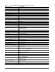
Command name Command code (in hex) Security Erase Unit F4H Security Freeze F5H Security Set Password F1H Security Unlock F2H Seek 70H Set Features EFH Set Max Address F9H Note: Individual Set Max Address commands are identified by the value placed in the Set Max Features register as defined to the right. Address: Password: Lock: Unlock: Freeze Lock: Set Max Address Extended 37H Set Multiple Mode C6H Sleep E6H S.M.A.R.T. Disable Operations B0H / D9H S.M.A.R.T.
4.3.1 Identify Device command The Identify Device command (command code ECH) transfers information about the drive to the host following power up. The data is organized as a single 512-byte block of data, whose contents are shown in Table 8 on page 27. All reserved bits or words should be set to zero. Parameters listed with an “x” are drive-specific or vary with the state of the drive. See Section 2.0 on page 3 for default parameter settings.
Word Description Value 60–61 Total number of user-addressable LBA sectors available (see Section 2.1 for related information) *Note: The maximum value allowed in this field is: 0FFFFFFFh (268,435,455 sectors, 137 Gbytes). Drives with capacities over 137 Gbytes will have 0FFFFFFFh in this field and the actual number of user-addressable LBAs specified in words 100-103. This is required for drives that support the 48-bit addressing feature.
Word Description Value 108–111 The mandatory value of the world wide name (WWN) for the drive. NOTE: This field is valid if word 84, bit 8 is set to 1 indicating 64-bit WWN support. Each drive will have a unique value. 112–127 ATA-reserved 0000H 128 Security status 0001H 129–159 Seagate-reserved xxxxH 160–254 ATA-reserved 0000H 255 Integrity word xxA5H Note. Advanced Power Management (APM) and Automatic Acoustic Management (AAM) features are not supported Note.
32 Bit Word 88 0 Ultra DMA mode 0 is supported. 1 Ultra DMA mode 1 is supported. 2 Ultra DMA mode 2 is supported. 3 Ultra DMA mode 3 is supported. 4 Ultra DMA mode 4 is supported. 5 Ultra DMA mode 5 is supported. 6 Ultra DMA mode 6 is supported. 8 Ultra DMA mode 0 is currently active. 9 Ultra DMA mode 1 is currently active. 10 Ultra DMA mode 2 is currently active. 11 Ultra DMA mode 3 is currently active. 12 Ultra DMA mode 4 is currently active.
4.3.2 Set Features command This command controls the implementation of various features that the drive supports. When the drive receives this command, it sets BSY, checks the contents of the Features register, clears BSY and generates an interrupt. If the value in the register does not represent a feature that the drive supports, the command is aborted. Power-on default has the read look-ahead and write caching features enabled.
4.3.3 S.M.A.R.T. commands S.M.A.R.T. provides near-term failure prediction for disc drives. When S.M.A.R.T. is enabled, the drive monitors predetermined drive attributes that are susceptible to degradation over time. If self-monitoring determines that a failure is likely, S.M.A.R.T. makes a status report available to the host. Not all failures are predictable. S.M.A.R.T. predictability is limited to the attributes the drive can monitor. For more information on S.M.A.R.T.
5.0 Seagate Technology support services Online services Internet For information regarding Seagate products and services, visit www.seagate.com. Worldwide support is available 24 hours daily by email for your questions. Presales Support: Presales@Seagate.com Technical Support: DiscSupport@Seagate.com Warranty Support: http://www.seagate.com/www/en-us/support/warranty_&_returns_assistance mySeagate my.seagate.com is the industry's first Web portal designed specifically for OEMs and distributors.
Customer Service Operations Warranty Service Seagate offers worldwide customer support for Seagate products. Seagate distributors, OEMs and other direct customers should contact their Seagate Customer Service Operations (CSO) representative for warrantyrelated issues. Resellers or end users of drive products should contact their place of purchase or Seagate warranty service for assistance. Have your serial number and model or part number available.
Index A ACA 18 acceleration 15 acoustics 16 Active 13 Active mode 13 actuator arm 10 AFR 17 Agency certification 17 altitude 14 Ambient temperature 14 ambient temperature 9, 10 Annualized Failure Rate 17 Annualized Failure Rate (AFR) 17 areal density 1, 8 ATA commands 27 Australia/New Zealand Standard AS/NZS3548 1995 18 Australian Communication Authority (ACA) 18 Australian C-Tick 18 Average latency 9 Average seek time 9 B buffer 9 C cables and connectors 22 cache 9 capacity 8 case temperature 14 CE mark
I I/O data-transfer rate 8 I/O duty cycle 17 Identify Device 27 Identify Device command 29 Idle 13, 27 Idle Immediate 27 Idle mode 10, 13 IEC950 17 Information Technology Equipment (ITE) 17 Initialize Device Parameters 27 Input noise ripple 13 input voltage 10 interface 8, 25 interference 18 internal data-transfer rate OD 8 is 9 ISO document 7779 16 ITE 17 Operating power 10 Operating shock 15 Operating vibration 15 P Physical characteristics 9 point-to-point 2, 22 Power consumption 10 power consumption 1
RMS read/write current 13 RoHS 19 RRL 18 S S.M.A.R.T. Disable Operations 28 S.M.A.R.T. Enable Operations 28 S.M.A.R.T. Enable/Disable Autosave 28 S.M.A.R.T. Execute Offline 28 S.M.A.R.T. implementation 27 S.M.A.R.T. Read Attribute Thresholds 28 S.M.A.R.T. Read Data 28 S.M.A.R.T. Read Log Sector 28 S.M.A.R.T. Return Status 28 S.M.A.R.T. Save Attribute Values 28 S.M.A.R.T.
40 DiamondMax 22 Serial ATA Product Manual, Rev.
Seagate Technology LLC 920 Disc Drive, Scotts Valley, California 95066-4544, USA Publication Number: 100544218, Rev. A, Printed in U.S.A.