
Computer Drive User Manual
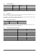
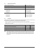
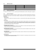
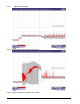
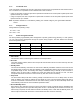
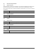
Table Of Contents
- 1.0 Introduction 1
- 2.0 Drive specifications 3
- 2.1 Formatted capacity 8
- 2.2 Default logical geometry 8
- 2.3 Recording and interface technology 8
- 2.4 Physical characteristics 9
- 2.5 Seek time 9
- 2.6 Start/stop times 10
- 2.7 Power specifications 10
- 2.8 Environmental specifications 14
- 2.9 Acoustics 16
- 2.10 Electromagnetic immunity 16
- 2.11 Reliability 17
- 2.12 Agency certification 17
- 2.13 Environmental protection 19
- 2.14 Corrosive environment 19
- 3.0 Configuring and mounting the drive 21
- 4.0 Serial ATA (SATA) interface 25
- 5.0 Seagate Technology support services 35
- Figure 1. Typical 5V startup and operation current profile 12
- Figure 2. Typical 12V startup and operation current profile 12
- Figure 3. Serial ATA connectors 22
- Figure 4. Attaching SATA cabling 22
- Figure 5. Mounting dimensions (1000 GB models) 23
- Figure 6. Mounting dimensions (320 and 160 GB models) 24
- 1.0 Introduction
- 2.0 Drive specifications
- 2.1 Formatted capacity
- 2.2 Default logical geometry
- 2.3 Recording and interface technology
- 2.4 Physical characteristics
- 2.5 Seek time
- 2.6 Start/stop times
- 2.7 Power specifications
- 2.8 Environmental specifications
- 2.9 Acoustics
- 2.10 Electromagnetic immunity
- 2.11 Reliability
- 2.12 Agency certification
- 2.13 Environmental protection
- 2.14 Corrosive environment
- 3.0 Configuring and mounting the drive
- 4.0 Serial ATA (SATA) interface
- 5.0 Seagate Technology support services
- Index

10 DiamondMax 22 Serial ATA Product Manual, Rev. A
2.6 Start/stop times
2.7 Power specifications
The drive receives DC power (+5V or +12V) through a native SATA power connector. See Figure 4 on page 22.
2.7.1 Power consumption
Power requirements for the drives are listed in the table on page 9. Typical power measurements are based on
an average of drives tested, under nominal conditions, using 5.0V and 12.0V input voltage at 25°C ambient
temperature.
• Spinup power
Spinup power is measured from the time of power-on to the time that the drive spindle reaches operating
speed.
• Seek mode
During seek mode, the read/write actuator arm moves toward a specific position on the disc surface and
does not execute a read or write operation. Servo electronics are active. Seek mode power represents the
worst-case power consumption, using only random seeks with read or write latency time. This mode is not
typical and is provided for worst-case information.
• Read/write power and current
Read/write power is measured with the heads on track, based on a 16-sector write followed by a 32-msec
delay, then a 16-sector read followed by a 32-msec delay.
• Operating power and current
Operating power is measured using 40 percent random seeks, 40 percent read/write mode (1 write for each
10 reads) and 20 percent drive idle mode.
• Idle mode power
Idle mode power is measured with the drive up to speed, with servo electronics active and with the heads in
a random track location.
• Standby mode
During Standby mode, the drive accepts commands, but the drive is not spinning, and the servo and read/
write electronics are in power-down mode.
1000 GB Models 320 and 160 GB Models
Power-on to Ready (sec) 20 (max) 9 (max)
Standby to Ready (sec) 15 (max) 9 (max)
Ready to spindle stop (sec) 10 (max)