
Computer Drive User Manual
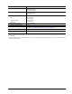
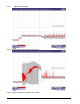
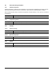
Table Of Contents
- 1.0 Introduction 1
- 2.0 Drive specifications 3
- 2.1 Formatted capacity 8
- 2.2 Default logical geometry 8
- 2.3 Recording and interface technology 8
- 2.4 Physical characteristics 9
- 2.5 Seek time 9
- 2.6 Start/stop times 10
- 2.7 Power specifications 10
- 2.8 Environmental specifications 14
- 2.9 Acoustics 16
- 2.10 Electromagnetic immunity 16
- 2.11 Reliability 17
- 2.12 Agency certification 17
- 2.13 Environmental protection 19
- 2.14 Corrosive environment 19
- 3.0 Configuring and mounting the drive 21
- 4.0 Serial ATA (SATA) interface 25
- 5.0 Seagate Technology support services 35
- Figure 1. Typical 5V startup and operation current profile 12
- Figure 2. Typical 12V startup and operation current profile 12
- Figure 3. Serial ATA connectors 22
- Figure 4. Attaching SATA cabling 22
- Figure 5. Mounting dimensions (1000 GB models) 23
- Figure 6. Mounting dimensions (320 and 160 GB models) 24
- 1.0 Introduction
- 2.0 Drive specifications
- 2.1 Formatted capacity
- 2.2 Default logical geometry
- 2.3 Recording and interface technology
- 2.4 Physical characteristics
- 2.5 Seek time
- 2.6 Start/stop times
- 2.7 Power specifications
- 2.8 Environmental specifications
- 2.9 Acoustics
- 2.10 Electromagnetic immunity
- 2.11 Reliability
- 2.12 Agency certification
- 2.13 Environmental protection
- 2.14 Corrosive environment
- 3.0 Configuring and mounting the drive
- 4.0 Serial ATA (SATA) interface
- 5.0 Seagate Technology support services
- Index

DiamondMax 22 Serial ATA Product Manual, Rev. A 13
2.7.2 Conducted noise
Input noise ripple is measured at the host system power supply across an equivalent 80-ohm resistive load on
the +12 volt line or an equivalent 15-ohm resistive load on the +5 volt line.
• Using 12-volt power, the drive is expected to operate with a maximum of 120 mV peak-to-peak square-wave
injected noise at up to 10 MHz.
• Using 5-volt power, the drive is expected to operate with a maximum of 100 mV peak-to-peak square-wave
injected noise at up to 10 MHz.
Note. Equivalent resistance is calculated by dividing the nominal voltage by the typical RMS read/write
current.
2.7.3 Voltage tolerance
Voltage tolerance (including noise):
5V +10% / -7.5%
12V +10% / -7.5%
2.7.4 Power-management modes
The drive provides programmable power management to provide greater energy efficiency. In most systems,
you can control power management through the system setup program. The drive features the following
power-management modes:
• Active mode
The drive is in Active mode during the read/write and seek operations.
• Idle mode
The buffer remains enabled, and the drive accepts all commands and returns to Active mode any time disc
access is necessary.
• Standby mode
The drive enters Standby mode when the host sends a Standby Immediate command. If the host has set
the standby timer, the drive can also enter Standby mode automatically after the drive has been inactive for
a specifiable length of time. The standby timer delay is established using a Standby or Idle command. In
Standby mode, the drive buffer is enabled, the heads are parked and the spindle is at rest. The drive
accepts all commands and returns to Active mode any time disc access is necessary.
•Sleep mode
The drive enters Sleep mode after receiving a Sleep command from the host. In Sleep mode, the drive
buffer is disabled, the heads are parked and the spindle is at rest. The drive leaves Sleep mode after it
receives a Hard Reset or Soft Reset from the host. After receiving a reset, the drive exits Sleep mode and
enters Standby mode with all current translation parameters intact.
• Idle and Standby timers
Each time the drive performs an Active function (read, write or seek), the standby timer is reinitialized and
begins counting down from its specified delay times to zero. If the standby timer reaches zero before any
drive activity is required, the drive makes a transition to Standby mode. In both Idle and Standby mode, the
drive accepts all commands and returns to Active mode when disc access is necessary.
Power modes Heads Spindle Buffer
Active Tracking Rotating Enabled
Idle Tracking Rotating Enabled
Standby Parked Stopped Enabled
Sleep Parked Stopped Disabled