
Computer Drive User Manual
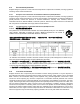

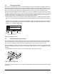
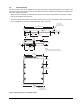
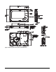
Table Of Contents
- 1.0 Introduction 1
- 2.0 Drive specifications 3
- 2.1 Formatted capacity 8
- 2.2 Default logical geometry 8
- 2.3 Recording and interface technology 8
- 2.4 Physical characteristics 9
- 2.5 Seek time 9
- 2.6 Start/stop times 10
- 2.7 Power specifications 10
- 2.8 Environmental specifications 14
- 2.9 Acoustics 16
- 2.10 Electromagnetic immunity 16
- 2.11 Reliability 17
- 2.12 Agency certification 17
- 2.13 Environmental protection 19
- 2.14 Corrosive environment 19
- 3.0 Configuring and mounting the drive 21
- 4.0 Serial ATA (SATA) interface 25
- 5.0 Seagate Technology support services 35
- Figure 1. Typical 5V startup and operation current profile 12
- Figure 2. Typical 12V startup and operation current profile 12
- Figure 3. Serial ATA connectors 22
- Figure 4. Attaching SATA cabling 22
- Figure 5. Mounting dimensions (1000 GB models) 23
- Figure 6. Mounting dimensions (320 and 160 GB models) 24
- 1.0 Introduction
- 2.0 Drive specifications
- 2.1 Formatted capacity
- 2.2 Default logical geometry
- 2.3 Recording and interface technology
- 2.4 Physical characteristics
- 2.5 Seek time
- 2.6 Start/stop times
- 2.7 Power specifications
- 2.8 Environmental specifications
- 2.9 Acoustics
- 2.10 Electromagnetic immunity
- 2.11 Reliability
- 2.12 Agency certification
- 2.13 Environmental protection
- 2.14 Corrosive environment
- 3.0 Configuring and mounting the drive
- 4.0 Serial ATA (SATA) interface
- 5.0 Seagate Technology support services
- Index
DiamondMax 22 Serial ATA Product Manual, Rev. A 15
2.8.5 Shock
All shock specifications assume that the drive is mounted securely with the input shock applied at the drive
mounting screws. Shock may be applied in the X, Y or Z axis.
2.8.5.1 Operating shock
These drives comply with the performance levels specified in this document when subjected to a maximum
operating shock of 70 Gs based on half-sine shock pulses of 2 msec. Shocks should not be repeated more
than two times per second.
2.8.5.2 Nonoperating shock
1000 GB models
The nonoperating shock level that the drive can experience without incurring physical damage or degradation
in performance when subsequently put into operation is 300 Gs based on a nonrepetitive half-sine shock pulse
of 2 msec duration.
320 and 160 GB models
The nonoperating shock level that the drive can experience without incurring physical damage or degradation
in performance when subsequently put into operation is 350 Gs based on a nonrepetitive half-sine shock pulse
of 2 msec duration.
2.8.6 Vibration
All vibration specifications assume that the drive is mounted securely with the input vibration applied at the
drive mounting screws. Vibration may be applied in the X, Y or Z axis.
2.8.6.1 Operating vibration
The maximum vibration levels that the drive may experience while meeting the performance standards speci-
fied in this document are specified below.
2.8.6.2 Nonoperating vibration
The maximum nonoperating vibration levels that the drive may experience without incurring physical damage
or degradation in performance when subsequently put into operation are specified below.
2–22 Hz 0.25 Gs (Limited displacement)
22–350 Hz 0.50 Gs
350–500 Hz 0.25 Gs
5–22 Hz 2.0 Gs (limited displacement)
22–350 Hz 5.0 Gs
350–500 Hz 2.0 Gs