
Computer Drive User Manual
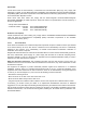

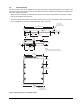
Table Of Contents
- 1.0 Introduction 1
- 2.0 Drive specifications 3
- 2.1 Formatted capacity 8
- 2.2 Default logical geometry 8
- 2.3 Recording and interface technology 8
- 2.4 Physical characteristics 9
- 2.5 Seek time 9
- 2.6 Start/stop times 10
- 2.7 Power specifications 10
- 2.8 Environmental specifications 14
- 2.9 Acoustics 16
- 2.10 Electromagnetic immunity 16
- 2.11 Reliability 17
- 2.12 Agency certification 17
- 2.13 Environmental protection 19
- 2.14 Corrosive environment 19
- 3.0 Configuring and mounting the drive 21
- 4.0 Serial ATA (SATA) interface 25
- 5.0 Seagate Technology support services 35
- Figure 1. Typical 5V startup and operation current profile 12
- Figure 2. Typical 12V startup and operation current profile 12
- Figure 3. Serial ATA connectors 22
- Figure 4. Attaching SATA cabling 22
- Figure 5. Mounting dimensions (1000 GB models) 23
- Figure 6. Mounting dimensions (320 and 160 GB models) 24
- 1.0 Introduction
- 2.0 Drive specifications
- 2.1 Formatted capacity
- 2.2 Default logical geometry
- 2.3 Recording and interface technology
- 2.4 Physical characteristics
- 2.5 Seek time
- 2.6 Start/stop times
- 2.7 Power specifications
- 2.8 Environmental specifications
- 2.9 Acoustics
- 2.10 Electromagnetic immunity
- 2.11 Reliability
- 2.12 Agency certification
- 2.13 Environmental protection
- 2.14 Corrosive environment
- 3.0 Configuring and mounting the drive
- 4.0 Serial ATA (SATA) interface
- 5.0 Seagate Technology support services
- Index
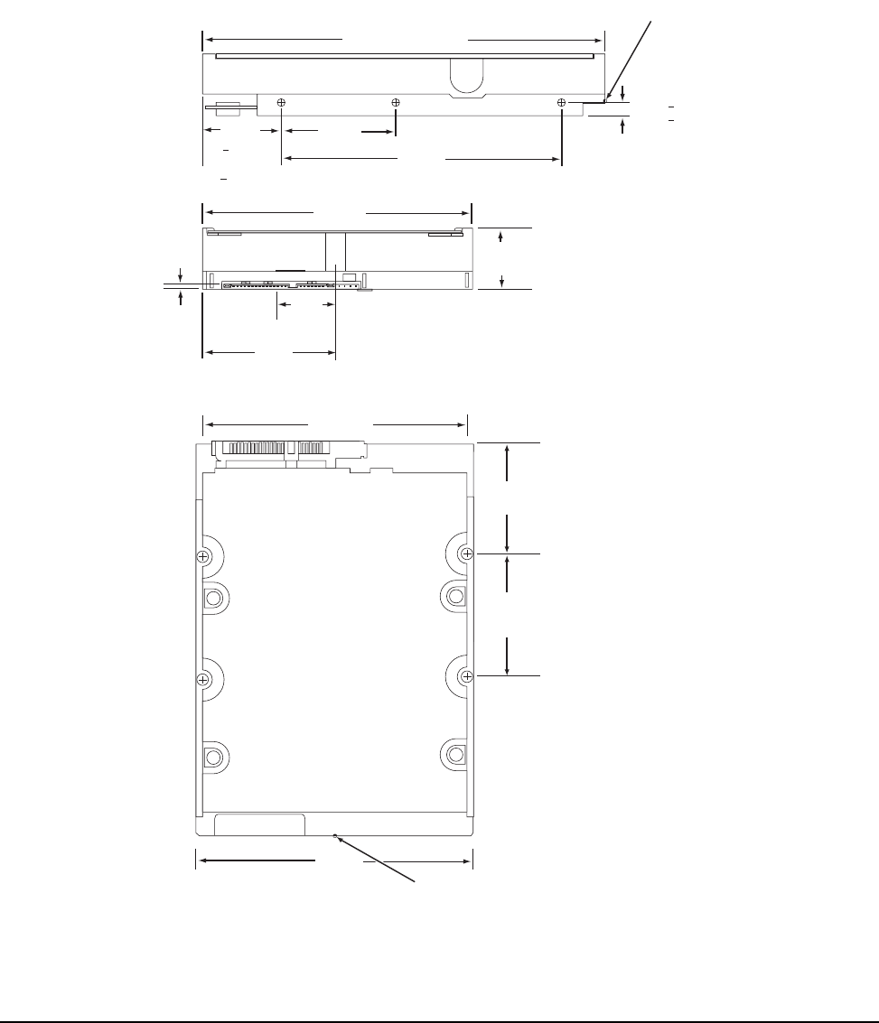
DiamondMax 22 Serial ATA Product Manual, Rev. A 23
3.4 Drive mounting
You can mount the drive in any orientation using four screws in the side-mounting holes or four screws in the
bottom-mounting holes. See Figure 5 for drive mounting dimensions. Follow these important mounting precau-
tions when mounting the drive:
• Allow a minimum clearance of 0.030 inches (0.76 mm) around the entire perimeter of the drive for cooling.
• Use only 6-32 UNC mounting screws.
• The screws should be inserted no more than 0.150 inch (3.81 mm) into the bottom or side mounting holes.
• Do not overtighten the mounting screws (maximum torque: 6 inch-lb).
Figure 5. Mounting dimensions (1000 GB models)
4.000
(101.6)
5.787 (146.9898) max.
1.028 max
(26.111 max)
2.00
(50.80)
1.638
(41.605)
4.000
(101.60)
2 x 1.750
(2 x 44.45)
2 x 3.750
(2 x 95.25)
C
L
of drive
[1]
Notes:
Dimensions are shown in inches (mm).
[1] Dimensions per SFF-8301 specification
[1]
[1]
[1]
1.122
+ .020
(28.499
+ .508)
[1]
[1]
[1]
[1]
C
L
of conn. Datum B
.814
(20.676)
.138
(3.505)
.250 + .015
(6.35 + .381)
(3x both sides)
4.000
(101.6)
2 x 1.625
(2 x 41.28)
[1]
Recommended
case temperature
measurement location
Recommended
case temperature
measurement location