
Computer Drive User Manual
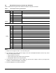
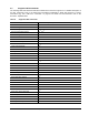
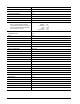
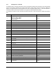
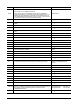
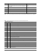

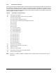
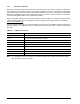
Table Of Contents
- 1.0 Introduction 1
- 2.0 Drive specifications 3
- 2.1 Formatted capacity 8
- 2.2 Default logical geometry 8
- 2.3 Recording and interface technology 8
- 2.4 Physical characteristics 9
- 2.5 Seek time 9
- 2.6 Start/stop times 10
- 2.7 Power specifications 10
- 2.8 Environmental specifications 14
- 2.9 Acoustics 16
- 2.10 Electromagnetic immunity 16
- 2.11 Reliability 17
- 2.12 Agency certification 17
- 2.13 Environmental protection 19
- 2.14 Corrosive environment 19
- 3.0 Configuring and mounting the drive 21
- 4.0 Serial ATA (SATA) interface 25
- 5.0 Seagate Technology support services 35
- Figure 1. Typical 5V startup and operation current profile 12
- Figure 2. Typical 12V startup and operation current profile 12
- Figure 3. Serial ATA connectors 22
- Figure 4. Attaching SATA cabling 22
- Figure 5. Mounting dimensions (1000 GB models) 23
- Figure 6. Mounting dimensions (320 and 160 GB models) 24
- 1.0 Introduction
- 2.0 Drive specifications
- 2.1 Formatted capacity
- 2.2 Default logical geometry
- 2.3 Recording and interface technology
- 2.4 Physical characteristics
- 2.5 Seek time
- 2.6 Start/stop times
- 2.7 Power specifications
- 2.8 Environmental specifications
- 2.9 Acoustics
- 2.10 Electromagnetic immunity
- 2.11 Reliability
- 2.12 Agency certification
- 2.13 Environmental protection
- 2.14 Corrosive environment
- 3.0 Configuring and mounting the drive
- 4.0 Serial ATA (SATA) interface
- 5.0 Seagate Technology support services
- Index

DiamondMax 22 Serial ATA Product Manual, Rev. A 27
4.3 Supported ATA commands
The following table lists Serial ATA standard commands that the drive supports. For a detailed description of
the ATA commands, refer to the Serial ATA International Organization: Serial ATA Revision 2.6 (http://
www.sata-io.org). See “S.M.A.R.T. commands” on page 34 for details and subcommands used in the
S.M.A.R.T. implementation.
Table 8: Supported ATA commands
Command name Command code (in hex)
Check Power Mode E5
H
Device Configuration Freeze Lock B1
H
/ C1
H
Device Configuration Identify B1
H
/ C2
H
Device Configuration Restore B1
H
/ C0
H
Device Configuration Set B1
H
/ C3
H
Device Reset 08
H
Download Microcode 92
H
Execute Device Diagnostics 90
H
Flush Cache E7
H
Flush Cache Extended EA
H
Format Track 50
H
Identify Device EC
H
Idle E3
H
Idle Immediate E1
H
Initialize Device Parameters 91
H
Read Buffer E4
H
Read DMA C8
H
Read DMA Extended 25
H
Read DMA Without Retries C9
H
Read Log Ext 2F
H
Read Multiple C4
H
Read Multiple Extended 29
H
Read Native Max Address F8
H
Read Native Max Address Extended 27
H
Read Sectors 20
H
Read Sectors Extended 24
H
Read Sectors Without Retries 21
H
Read Verify Sectors 40
H
Read Verify Sectors Extended 42
H
Read Verify Sectors Without Retries 41
H
Recalibrate 10
H
Security Disable Password F6
H
Security Erase Prepare F3
H