
Computer Drive User Manual
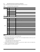
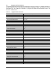
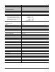

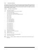
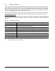
Table Of Contents
- 1.0 Introduction 1
- 2.0 Drive specifications 3
- 2.1 Formatted capacity 8
- 2.2 Default logical geometry 8
- 2.3 Recording and interface technology 8
- 2.4 Physical characteristics 9
- 2.5 Seek time 9
- 2.6 Start/stop times 10
- 2.7 Power specifications 10
- 2.8 Environmental specifications 14
- 2.9 Acoustics 16
- 2.10 Electromagnetic immunity 16
- 2.11 Reliability 17
- 2.12 Agency certification 17
- 2.13 Environmental protection 19
- 2.14 Corrosive environment 19
- 3.0 Configuring and mounting the drive 21
- 4.0 Serial ATA (SATA) interface 25
- 5.0 Seagate Technology support services 35
- Figure 1. Typical 5V startup and operation current profile 12
- Figure 2. Typical 12V startup and operation current profile 12
- Figure 3. Serial ATA connectors 22
- Figure 4. Attaching SATA cabling 22
- Figure 5. Mounting dimensions (1000 GB models) 23
- Figure 6. Mounting dimensions (320 and 160 GB models) 24
- 1.0 Introduction
- 2.0 Drive specifications
- 2.1 Formatted capacity
- 2.2 Default logical geometry
- 2.3 Recording and interface technology
- 2.4 Physical characteristics
- 2.5 Seek time
- 2.6 Start/stop times
- 2.7 Power specifications
- 2.8 Environmental specifications
- 2.9 Acoustics
- 2.10 Electromagnetic immunity
- 2.11 Reliability
- 2.12 Agency certification
- 2.13 Environmental protection
- 2.14 Corrosive environment
- 3.0 Configuring and mounting the drive
- 4.0 Serial ATA (SATA) interface
- 5.0 Seagate Technology support services
- Index

DiamondMax 22 Serial ATA Product Manual, Rev. A 33
4.3.2 Set Features command
This command controls the implementation of various features that the drive supports. When the drive receives
this command, it sets BSY, checks the contents of the Features register, clears BSY and generates an inter-
rupt. If the value in the register does not represent a feature that the drive supports, the command is aborted.
Power-on default has the read look-ahead and write caching features enabled. The acceptable values for the
Features register are defined as follows:
Note. At power-on, or after a hardware or software reset, the default values of the features are as indi-
cated above.
Table 9: Set Features command values
02
H
Enable write cache (default).
03
H
Set transfer mode (based on value in Sector Count register).
Sector Count register values:
00
H
Set PIO mode to default (PIO mode 2).
01
H
Set PIO mode to default and disable IORDY (PIO mode 2).
08
H
PIO mode 0
09
H
PIO mode 1
0A
H
PIO mode 2
0B
H
PIO mode 3
0C
H
PIO mode 4 (default)
20
H
Multiword DMA mode 0
21
H
Multiword DMA mode 1
22
H
Multiword DMA mode 2
40
H
Ultra DMA mode 0
41
H
Ultra DMA mode 1
42
H
Ultra DMA mode 2
43
H
Ultra DMA mode 3
44
H
Ultra DMA mode 4
45
H
Ultra DMA mode 5
46
H
Ultra DMA mode 6
10
H
Enable use of SATA features
55
H
Disable read look-ahead (read cache) feature.
82
H
Disable write cache
90
H
Disable use of SATA features
AA
H
Enable read look-ahead (read cache) feature (default).
F1
H
Report full capacity available