
Product manual


Installation
DiamondMax Plus8 20/30/40GB AT 4-5
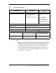
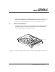
Figure 4-4 Jumper Locations on the Interface Connector
The configuration of the following Three jumpers controls the drive’s
five modes of operation:
• CS – Cable Select
• DS – Drive Select
• PK– Jumper Parking Position (Slave mode)
• AC– Alternate Capacity
The AT PCB has two jumper locations provided to configure the drive in
a system. The default configuration for the drive as shipped from the
factory is with a jumper across the DS location, and open positions in
the CS, PK and AC positions.
Table 4-1 defines the operation of the master/slave jumpers and their
function relative to pin 28 on the interface. 1 indicates that the specified
jumper is installed; 0 indicates that the jumper is not installed.
AT Interface Connector
Back of Drive
Cable
Select
Setting
DS
CS
PK
DS
CS
PK
AC
Master
Setting
DS
CS
PK
AC
Default Jumper
Setting
(This is identical for both drive 0 and drive 1)
DS with CS
for Slaves not
supporting DASP
DS
CS
PK
AC
Slave
Setting
DS
CS
PK
AC
Jumper in
Park Position