
Product manual


Installation
DiamondMax Plus8 20/30/40GB AT 4-9
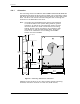
CAUTION: The PCB is very close to the mounting holes. Do not exceed the specified penetration for the
mounting screws. The specified screw penetration allows full use of the mounting hole threads,
while avoiding damaging or placing unwanted stress on the PCB. Figure 4-7 specifies the mini-
mum clearance between the PCB and the screws in the mounting holes.
The Maxtor hard drive design allows greater shock tolerance than that afforded by larger, heavi-
er drives. The drive may be mounted in any attitude using four size 6-32 screws with 3 mm
maximum penetration and a maximum torque of 5-inch pounds. Allow adequate ventilation to
the drive to ensure reliable operation.
Figure 4-6
Mounting Screw Clearance
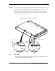
4.4 MOUNTING
Drive mounting orientation, clearance, and ventilation requirements are
described in the following subsections.
Printed-
Circuit
Board
Head/Disk
Assembly
Printed-
Circuit
Board
Drive
Mounting
Screw
3.00 mm Maximum
3.00 mm Maximum