
Product manual


ATA Bus Interface and ATA Commands
DiamondMax Plus8 20/30/40GB AT 5-13
93 Hardware reset result. The contents of bits (12:0) of this word shall change only
during the execution of a hardware reset
15: Shall be cleared to zero.
14: Shall be set to one.
13: 1 = device detected CBLID- above ViH. 0 = device detected CBLID- below
ViL
12-8: Device 1 hardware reset result. Device 0 shall clear these bits to zero.
Device shall set these bits as follows:
12: Reserved.
11: 0 = Device 1 did not assert PDIAG-.
1 = Device 1 asserted PDIAG-.
10-9: These bits indicate how Device 1 determined the device number:
00 = Reserved.
01 = a jumper was used.
10 = the CSEL signal was used.
11 = some other method was used or the method is unknown.
8: Shall be set to one.
7-0: Device 0 hardware reset result. Device 1 shall clear these bits to zero.
Device shall set these bits as follows:
7: Reserved.
6: 0 = Device 0 does not respond when Device 1 is selected.
1 = Device 0 responds when Device 1 is selected.
5: 0 = Device 0 did not detect the assertion of DASP-.
1 = Device 0 detected the assertion of DASP-
4: 0 = Device 0 did not detect the assertion of PDIAG-.
1 = Device 0 detected the assertion of PDIAG-.
3: 0 = Device 0 failed diagnostics.
1 = Device 0 passed diagnostics.
2-1: These bits indicate how Device 0 determined the device number:
00 = Reserved.
01 = a jumper was used.
10 = the CSEL signal was used.
11 = some other method was used or the method is unknown.
0: Shall be set to one.
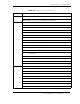
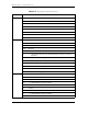
Table 5-2 Identify Drive Command Parameters
Word CONTENT DESCRIPTION