Digital Video Recorder User Manual CBC V 0.
Table of Contents 1. Introduction 1-1 Safety Warning ……………………………………………………………………………..…… 3 1-2 Features ……………………………………………………………………………………..…… 4 1-3 Specifications ………………………………………………………………………………..…... 5 2. Installation 2-1 Package contents ………………………………………………………………………………. 6 2-2 Connection ………………………………………………………………………………………. 6 2-3 RS232 Remote protocol ………………………………………………………………………..… 7 3. Configuration 3-1 Install HDD ……………………………………………………………………………………… 8 3-2 Front panel keypad ……………………………………………………………………………..
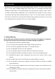
1. Introduction We thank you for choosing this high quality Digital Video Recorder. The DVR converts analog NTSC or PAL video to digital images and records them on a removable hard disk drive. Digitally recorded video has several advantages over analog video recorded on tape. There is no need to adjust tracking. Digital video can be indexed by time schedule or events, and you can instantly view video after selecting the time or event.
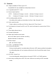
1.2 Features 1.2.1 Replace traditional Time-Lapse VCR. Compatible with most multiplexer and quad processors. 1.2.2 Compatible with NTSC / PAL 1.2.3 Record speed options: NTSC : Maximum 60 Images / second, minimum 1 Image / second PAL : Maximum 50 Images / second, Minimum 1 Image / second 1.2.4 Recording quality selection Recording video quality and resolution for Best / High / Normal / Basic 1.2.5 Quick search modes Search video by Last Record, Full List, Alarm List & Time Search 1.2.
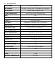
1.3 Specifications VIDEO FORMAT NTSC / EIA or PAL / CCIR HDD STORAGE IDE type, UTMA 66 above, 1 removable HDD supported RECORD MODE Manual / Alarm / External / Timer PLAYBACK SEARCHING Date & Time / Event / Alarm searching RS232 Yes O.S.D.
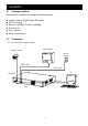
2. Installation 2.1 Package contents The package contents including the following items. z z z z z z Single channel Digital Video Recorder HDD cartridge Key for cartridge (In HDD cartridge) Power cord User manual Rack mounting kit 2.2 Connection 2.2.
2.2.2 Connect with Multiplexer Video Camera 16 .. . . 2 Main Monitor 1 Alarm Sensor .. . . Alarm Input PC RS232 GND VCR OUT VCR IN DVR 2.3 RS232 Remote Protocol You can use the PC key board to simulate DVR key pad. DATA: REMOTE PROTOCOL using 8 bit data、1 start bit、1stop bit ACT (FFH) FUNCTION MENU ENTER SEARCH SLOW UP / PAUSE C0H ID FUNCTION STOP (7FH) CODE ASCII FUNCTION CODE ASCII 0x4D 0x0D 0x48 0x53 0x55 M ENTER H S U DOWN / STOP LEFT / F.F. RIGHT / F.R.
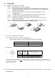
3.1 Install HDD 3.1.1 Installing Hard Drive into Cartridge 3.1.1.1. Please find the Key in the Cartridge. 3.1.1.2. Pull the active-handle outwards and use the miniature key provided and insert into the key hole, turning the key anti-clockwise, then the handle will auto-eject for pulling out.。 3.1.1.3. Pull the handle outwards to remove the carrier body away from the cartridge frame. 3.1.1.4. Push the open button to slide the top cover backwards and remove. 3.1.1.5.
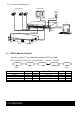
PAL/NTSC SYSTEM (Unit : hours) Fields Delay Best Record High Quality Normal Basic 1 2 4 6 8 12 24 32 40 48 56 64 12 24 48 72 96 144 192 240 288 384 480 576 672 768 15 30 60 90 120 180 240 300 360 480 600 720 840 960 24 48 96 144 192 288 384 480 576 768 960 1152 1344 1536 40 80 160 240 320 480 640 800 960 1280 1600 1920 2240 2560 HDD Type 16 20 120GB Note: Above data is from actual test by recording normal TV program. (Reference only) 3.
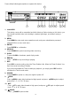
Please follow following descriptions to operate this device. 13 HDD MENU 1 ENTER SEARCH ALARM TIMER HDD FULL SLOW REW 2 3 4 5 FF STOP 9 10 11 6 PLAY REC POWER 12 7 8 1. Install HDD This device comes with a removable hard disk drive tray. Before turning on this device, you must install hard disk drive (not including in standard (package), and make it ready to operate. 2. MENU Press MENU to enter main menu operation mode, and press administrator password (default:0000) to access main menu.
12. PLAY Press PLAY to play recorded video. 13. LED Light: Under following condition, the led light is ON. (1) HDD : HDD is activated (2) HDD FULL:HDD is full (3) ALARM:When Alarm Enable : Yes (when alarm is triggered, the led is flashing) (4) TIMER:When Timer Enable : Yes (5) PLAY:Play operation (6) REC:Recording operation (7) POWER : Power On/Off 3.3 Back panel connection 4 1 VIDEO IN POWER ALARM VIDEO OUT 2 3 1. VIDEO IN Connect to video source, such as quad, multiplexer, or camera. 2.
25 pin com port 9 pin com port 12
PIN 1. RS232-TX : RS-232 DVR can be controlled remotely by an external device or control system, such as a control keyboard, using RS-232 serial communications signals. PIN 2. RS232-RX : RS-232 DVR can be controlled remotely by an external device or control system, such as a control keyboard, using RS-232 serial communications signals. PIN 3. VIDEO LOSS When video loss happen, it will send a signal to trigger another accessory.
alarm triggered, COM disconnect with NC, and connect with NO. PIN 8. EXTERNAL ALARM NO Under normal operation COM connect with NC and disconnect with NO. But when Alarm triggered, COM disconnect with NC, and connect with NO. PIN 9. GND GROUND PIN 10. RS485-B DVR can be controlled remotely by an external device or control system, such as a control keyboard, using RS485 serial communications signals. PIN 11.
To press ”MENU” to enter main menu. You will need to enter password to access main menu. To press “◄” “►” to move digit, and to press ” ▲” “▼” to select number. To press ”ENTER” button to confirm password. Ex.: Password : 0000 Password : 0000 (Default : 0000) After keying in correct password, and confirm by pressing ”ENTER” button, screen will show following options.
To press ”▲” “▼” to choose item. (Menu) Timer Record Alarm Remote ► System Event Timer Record Alarm Remote ► System Event To choose System item, and press “ENTER” button to enter System Setup mode. It will be shown as right screen (System) ► Buzzer : On HDD Overwrite : No Message Latch : No Date Display : Y- M - D Date : 2002-JUL-14(SUN) Time : 22:38:29 New Password : xxxx Clear HDD : No. System Reset : No. 3.5.1 Internal Alarm Buzzer ON/OFF setup: 3.5.1.1 Press ”▲” “▼” to choose Buzzer 3.5.1.
3.5.2.1 Press ”▲” “▼” to choose Message Latch 3.5.2.2 Press “Enter” to confirm Message Latch 3.5.2.3 Press ”▲” “▼” to choose Message Latch : Yes / No Yes : Turn Message Latch on, the message will show in the screen. No : Turn Message Latch off, the message will retain only 10 seconds. 3.5.2.4 Press Menu to exit and confirm the current operation. 3.5.2.5 Press again Menu to exit and close System Setup mode 3.5.4 On Screen Display ( date display ) format : Y-M-D, M-D-Y, D-M-Y, and OFF 3.5.4.
3.5.7.1 Press ”▲” “▼” to choose new password : xxxx setup. 3.5.7.2 Press “Enter” to confirm new password : xxxx setup. 3.5.7.3 Press ”▲” “▼” to choose number, and press “◄” “ ►” to move digit location. 3.5.7.4 Press Menu to exit and confirm current operation. 3.5.7.5 Press again Menu to exit and close System Setup mode 3.5.8 Clear HDD Yes / No setup 3.5.8.1 Press ”▲” “▼”to choose clear HDD setup. 3.5.8.2 Press “Enter” to confirm clear HDD setup. 3.5.8.3 Press ”▲” “▼”to choose clear HDD setup Yes or No.
No : Confirm not to System Reset 3.5.9.4 Press Menu to exit and confirm current operation. 3.5.9.5 Press again Menu to exit and close System Setup mode. Note: If operation without any action until 60 seconds, it will close the setup mode. 3.6 Schedule Time-Lapse record mode setup (Timer) 3.6.1 Enter “ Timer “ setup To press ”MENU” to enter main menu. You will need to enter password to access main menu. To press “◄” “►” to move digit, and to press ”▲” “▼” to select number.
To choose Timer item, and press “ENTER” button to confirm Timer Record setup mode. It will be shown as right screen (Timer) Day Start End Daily 00:00 00:00 Daily 00:00 00:00 Daily 00:00 00:00 Daily 00:00 00:00 Daily 00:00 00:00 Daily 00:00 00:00 Daily 00:00 00:00 Timer Enable: No F-D Off Off Off Off Off Off Off 3.6.2 Timer Record Setup: 3.6.2.1 Press “Enter” to confirm Timer Record day setup. 3.6.2.
No : To confirm no Timer Enable:No Scheduling Timer Record function 3.6.2.8 Press Menu to exit and confirm current operation. 3.6.2.9 Press again Menu to exit and close System Setup mode. 3.7 Record mode setup 3.7.1 Enter “ Record “ setup To press ”MENU” to enter main menu. You will need to enter password to access main menu. To press “◄” “►” to move digit, and to press ”▲” “▼” to select number. To press ”ENTER” button to confirm password. Ex.
To choose Record item, and press “ENTER” to enter Record mode. It will be shown as right screen (Record) ► Fields Delay (F-D) : 01 Record Quality: Normal Record Mode: Frame 3.7.2 Fields Delay : 3.7.2.1 Press “Enter” to confirm “Fields Delay” setup . 3.7.2.2 Press ”▲” “▼” to choose “Fields Delay” setup. PAL/NTSC-1, 2, 4, 6, 8, 12, 16, 20, 24, 32, 40, 48, 56, 64 3.7.2.3 Press Menu to exit and confirm current operation. 3.7.2.4 Press again Menu to exit and close System Setup mode. 3.7.
To press ”MENU” to enter main menu. You will need to enter password to access main menu. To press “◄” “►” to move digit, and to press ”▲” “▼” to select number. To press ”ENTER” button to confirm password. Ex.: Password : 0000 Password : 0000 (Default : 0000) After keying in correct password, and confirm by pressing ”ENTER” button, screen will show following (Menu) ► Timer Record Alarm Remote System Event options.
3.8.2.4 Press again Menu to exit and close System Setup mode. 3.8.3 Alarm Duration Setup option: 3.8.3.1 Press “Enter” to confirm Alarm Duration setup. 3.8.3.2 Press ”▲” “▼”to choose Alarm Duration 10 Sec, 15 Sec, 20 Sec, 30 Sec, 1 Min, 2 Min, 3 Min, 5 Min、10 Min、15 Min, 30 Min, Always。 3.8.3.3 Press Menu to exit and confirm current operation. 3.8.3.4 Press again Menu to exit and close System Setup mode. 3.8.4 Alarm Record Speed (Fields Delay) setup. 3.8.4.
To press ”MENU” to enter main menu. You will need to enter password to access main menu. To press “◄” “►” to move digit, and to press ”▲” “▼” to select number. To press ”ENTER” button to confirm password. Ex.: Password : 0000 Password : 0000 (Default : 0000) After keying in correct password, and confirm by pressing ”ENTER” button, screen will show following (Menu) ► Timer Record Alarm Remote System Event options.
3.9.2.3 Press Menu to exit and confirm current operation. 3.9.2.4 Press again Menu to exit and close System Setup mode. 3.9.3 Remote protocol Transmitting Baud Rate setup 3.9.3.1 Press “Enter” to confirm Baud Rate setup. 3.9.3.2 Press ”▲” “▼” to choose the Baud Rate 115200、57600、19200、9600、4800、3600、2400、1200。 3.9.3.3 Press Menu to exit and confirm current operation. 3.9.3.4 Press again Menu to exit and close System Setup mode. 3.9.
Press ”▲” “▼” to choose Event item. (Menu) Timer Record Alarm Remote System ►Event Timer Record Alarm Remote System ►Event Press “ENTER” to confirm Full List, and the screen will be as right displayed. Press ”▲” “▼” to choose wanted recorded event (There will be shown only 8 list in one page.), and Press “◄” “ ►” to change the pages.
set as Master, and screen will display as “HDD Master Connect”. If HDD is set as Slave, and screen will display as “HDD Slave Connect”. In order to shorten the power on running time, we suggest set the HDD as Master. After set DVR power on, POWER LED will turn to green color. (You can set up HDD to be Master or Slave by jumper setting on HDD.) 4.2 Recording Your DVR offers a variety of flexible recording modes.
The screen will be as right displayed. E : External trigger record : Recording OW : HDD Over Write 32GB : If the OW location shows 32GB, it means that HDD left 32 GB capacity for video recording. 2002 – JAN –01 01:02:03 E OW 4.2.3 Timer Record DVR will follow Timer setup to record, and the recording speed and quality will be followed TIMER recording mode setup in main menu. The screen will be as right displayed.
4.3.1.1 Press “PLAY” then press”►►” for fast forward searching screen. To press once ”►►” to get speed for 2X. To press twice “►►” to get speed for 4X, …and the maximum speed can be 32X. 4.3.1.2 Press “PLAY” then Press”◄◄” for fast rewind searching screen. To press once “◄◄” to get speed for 2X. To press twice “◄◄” to get speed for 4X, … and the maximum speed can be 32X. 4.3.2 Slow Forward (S.F.) & Slow Rewind (S.R.) 4.3.2.
Last Record - The last recorded video Full List - Recorded video full list sorting by time Alarm List - Alarm recorded list sorting by time Time Search - Find indicated time for recorded video 4.4.2 ►Last Record Full List Alarm List Time Search Search and play Last Record video Press ”▲” “▼”Button to choose Last Record item. Screen will be as right displayed. Press “Enter” to play the last recorded video ►Last Record Full List Alarm List Time Search 4.4.
Press ”▲” “▼” to choose Alarm List. Screen will be as right displayed. Last Record Full List ►Alarm List Time Search Press “ENTER” to confirm Full List, and the screen will be as right displayed. Press ”▲” “▼” to choose wanted recorded event (There will be shown only 8 list in one page.), and Press “◄” “ ►” to change the pages. Press “ENTER” to Play selected recorded video 4.4.
5. Trouble shouting & Appendix 5.1 Trouble shouting What DVR appears a malfunction, it may be not serious and can be corrected. The table below describes some typical problems and their remedies. Check them before calling your DVR dealer: PROBLEM No power REMEDY z Check power source cord connections. z Confirm that there is power at the outlet. Not working when press any z Check if it is under Key Lock mode. button z Press “MENU” & “ENTER” at same time to skip Key Lock mode.
5.
5.