HVR-04E Installation Guide v 1.
FCC Compliance Statement Caution: Any changes or modifications in construction of this device which are not expressly approved the party responsible for compliance could void the user's authority to operate the equipment. NOTE: This equipment has been tested and found to comply with the limits for a Class B digital device, pursuant to part 15 of the FCC Rules. These limits are designed to provide reasonable protection against harmful interference in a residential installation.
Important Notice 1. Do not place heavy objects on the top of the HVR-04E. 2. HVR-04E is for indoor use. It is not weatherproof. Use HVR-04E with referring to its environmental specifications (Temperature & Humidity). To clean the HVR-04E, gently wipe the outside with a clean dry cloth. 3. Be sure to use a DC adapter that is provided by Hunt Electronic USA, Inc. Connecting HVR-04E directly to an AC current will cause electric damages to HVR-04E. 4. Be careful not to drop the HVR-04E.
HVR-04E TABLE OF CONTENTS OVERVIEW ................................................................................................................................ 7 1. What is HVR-04E?.............................................................................................................. 7 2. Supplied Accessories........................................................................................................ 8 3. Description & Function ...................................................
TABLE OF CONTENTS 8.2.2. Daylight Saving ................................................................................................... 23 8.2.3. Time Format ........................................................................................................ 24 8.2.4. Date..................................................................................................................... 24 8.2.5. Time .........................................................................................
HVR-04E TABLE OF CONTENTS 14.3. Available HDD......................................................................................................... 37 14.4. Registering & Formatting HDD................................................................................ 38 15. Network Monitoring & Managing ................................................................................ 39 15.1. Connecting Ethernet .......................................................................................
OVERVIEW HVR-04E OVERVIEW 1. What is HVR-04E? The HVR-04E is a 4-Analog, 12-IP channel network digital video recorder. The HVR-04E can record and display 4 analog video channels and 12 IP video channels simultaneously. Video, Audio, and Text EventLogs are digitized and stored on two internal hard-drives.
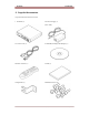
HVR-04E OVERVIEW 2. Supplied Accessories Unpack and check all the items as below. 1. HVR-04E (1) 2. DC Power Supply (1) (110V~220V) 3. AC Power Cord (1) 4. CD-ROM (Including DVR Manager) (1) 5. Remote Controller (1) 6. Guide (2) 7. Plug Bracket (1) 8. HDD Fixing Screw (8) 8 2003.05.21 (v 1.0) Hunt Electronic USA, Inc.
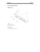
OVERVIEW 3.
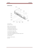
HVR-04E OVERVIEW HVR-04E Rear (7) Power switch (8) Ethernet connector (9) BNC connector for Video input (10) Audio input / output connector (11) RS232 connecter (9Pin D-Sub) (12) Terminal block for RS232 & 422/485 (13) Terminal block for Sensor input (14) Terminal block for Relay output (15) Video output for MONITOR or VCR (16) Video input type/impedance select & remote controller switch (17) IEEE1394 connecter (18) USB connecter (19) Power connector (DC12V) (20) GND 10 2003.05.21 (v 1.
INSTALLATION AND CONNECTION HVR-04E INSTALLATION AND CONNECTION 4. Connecting & Running HVR-04E 4.1. Connecting camera (1) Connect CCTV camera to HVR-04E with BNC cable as shown below. (2) Set video type (NTSC/PAL) by rear panel’s switch. The video type for all channels should be either NTSC or PAL. NTSC is the standard used in North America. (3) Set the impedance control switch for each channel as needed.
HVR-04E INSTALLATION AND CONNECTION 4.2. Connecting Monitor (1) Connect CCTV monitor to HVR-04E with BNC cable as shown below. HVR-04E has two video output ports ; for Monitor and VCR. The output signals from the two ports are same and either port may be used. 4.3. Connecting Audio (1) Connect audio signal to HVR-04E. 12 2003.05.21 (v 1.0) Hunt Electronic USA, Inc.
INSTALLATION AND CONNECTION HVR-04E
HVR-04E INSTALLATION AND CONNECTION 4.4. Supplying Power (1) Connect power cable to HVR-04E. (2) Turn on the power switch located on the HVR-04E rear panel. Use the plug bracket to secure the power cable if needed. To connect EARTH, refer to the following picture. 14 2003.05.21 (v 1.0) Hunt Electronic USA, Inc.
INSTALLATION AND CONNECTION HVR-04E 5. Running OSD menu 5.1. Using menu Press the [MENU] button to open the OSD Configuration Menu. (1) Main Menu (2) Sub-menu (3) Setting Page (4) Help message (1) Main Menu Tabs: The selected tab is shown in blue and the related sub-menus will be shown below the tab. To move to the previous/next Main Menu Tab, use the [◄◄ / ►►] arrow buttons. To move to a sub-menu, press the [ENTER] or [▼] buttons.
HVR-04E INSTALLATION AND CONNECTION 5.2. Dialogue Box to Edit a Word There are two methods to set word. (1) Using number button Enter the related numbers in order of horizontal/vertical. (For example, in order to select “C”, press [3] and [2] buttons.) (2) Using arrow button Select a value using the [◄◄ / ►►] or [▲/▼] buttons. The intersection of the horizontal and vertical bar is selected value. Press the [►] button to confirm the selected value.
INSTALLATION AND CONNECTION HVR-04E 6. Setting remote controller 6.1. Setting remote control DIP switch Set the remote control DIP switch to “ON.” 6.2. Set ID of HVR-04E When controlling several HVR-04Es with one remote controller, set Remote Control ID as follows. (1) Press [MENU] button. (2) Select “System” with using [►►] button and press the [ENETR] or [▼] button.
HVR-04E INSTALLATION AND CONNECTION (3) Select “Miscellaneous” from the sub-menu list using the [▼] button and press the [ENETR] button. (4) Select “Remote Control ID,” and press the [ENETR] button. (5) Select a value using the [◄◄ / ►►] buttons and press the [EXIT] button. (6) Press the [EXIT] button to exit the Settings Page and return to Monitor mode. Remote Control ID Up to 16 HVR-04Es can be controlled with a single remote controller. 6.3.
INSTALLATION AND CONNECTION HVR-04E 6.4. Operable range of remote controller 6.5. Loading the batteries into remote controller Remote controller requires two AAA-type batteries. 1. Remove the battery cover. 2. Taking care that the poles(+/-) are correctly positioned Batteries are not included as a packing accessory. 3. Replace the battery cover.
HVR-04E INSTALLATION AND CONNECTION 7. HVR-04E Configuration 7.1. Basic Configuration 7.2. Advanced Configuration 20 2003.05.21 (v 1.0) Hunt Electronic USA, Inc.
INSTALLATION AND CONNECTION 7.3. External Storage & Backup Configuration 7.4.
HVR-04E 8. INSTALLATION AND CONNECTION HVR-04E Basic Setting 8.1. Viewing Image After initial start-up, images from Ch.1~4 are displayed in a quad-split screen. If user password is set, a prompt for entering the password will appear. 22 2003.05.21 (v 1.0) Hunt Electronic USA, Inc.
INSTALLATION AND CONNECTION HVR-04E 8.2. Setting Date & Time (1) Press [MENU] button, and select “Quick Setup” tab. (2) Select “Date/Time” and enter the Settings Page by pressing [ENTER]. 8.2.1. Time Zone (1) Select “Time Zone” and press [ENETR] button to configure. (2) Select a value using the [◄◄ / ►►] button and press the [EXIT] button when finished. 8.2.2. Daylight Saving (1) “Daylight Saving Time” is only activated for time zones that use Daylight Savings.
HVR-04E INSTALLATION AND CONNECTION 8.2.3. Time Format (1) Select “Time Format” using the [◄◄ / ►►] or the [▲/▼] buttons and press [ENTER]. (2) Two Time Formats are available; ‘MM/DD/YYYY’ and ‘YYYY/MM/DD’. Select a value using [▲/ ▼] buttons, and press the [EXIT] button when finished. (Default value is ‘MM/DD/YYYY’.) 8.2.4. Date (1) Select “Date” using the [◄◄ / ►►] or the [▲/▼] buttons and press [ENTER].
INSTALLATION AND CONNECTION HVR-04E 8.3. Setting Recording Condition Recording conditions under the “Quick Setup” menu tab apply the same values to all analog channels 1~4. All settings are applied for 24 hours/day regardless of the values set for “Time Schedule” or “Alarm Rec.
HVR-04E INSTALLATION AND CONNECTION (1) Press [MENU] button, and select “Quick Setup.” (2) Move to sub-menu by pressing [ENTER] or the [▼] button. (3) Select “Recording” using the [▲/▼] buttons and press the [ENTER] button. 8.3.1. Configuration Status Displays the recording configuration status. When setting up through the “Quick Setup” menu, “Quick Setup” will be shown. When setting up through “Normal Rec.” or “Alarm Rec.,” “Custom Setup” will be shown.
INSTALLATION AND CONNECTION 8.3.5. Quality When “Recording Speed/Quality” is set as “Custom,” values can be set manually. (1) Select “Quality” using [▲/▼] buttons and press the [ENTER] button. (2) Select a value using the [◄◄ / ►►] button. Press the [EXIT] button when finished. 8.3.6. Audio Recording (1) Select “Audio Recording” using [▲/▼] buttons and press the [ENTER] button. (2) Select a value using the [◄◄ / ►►] button. Press the [EXIT] button when finished. 8.3.7.
HVR-04E INSTALLATION AND CONNECTION 9. Connecting and Configuring Sensor 9.1. Connecting Sensor Input To connect a sensor to S1, fix the wire to “S1” and “G“. Devices connected to the sensor input should have “Dry contact.” The following diagram is of an electric circuit with approximately 12mA flows. 28 2003.05.21 (v 1.0) Hunt Electronic USA, Inc.
INSTALLATION AND CONNECTION HVR-04E 9.2. Setting Sensor at OSD menu After a sensor is connected, it can be activated through the OSD Configuration menu. Select the sensor number (S1, S2, etc.) and press the [Enter] button to configure. Use the [◄◄ / ►►] buttons to select “On” or “Off.” Press [EXIT] when finished.
HVR-04E INSTALLATION AND CONNECTION 10. Connecting & Configuring Relay Out 10.1. Connecting Relay Out HVR-04E has total four ports of Relay Out. To connect a device to “O1,” connect the wires to two “O1”s. The rated voltage and current of Relay Out are as follows. Do not exceed the rated values. 24V DC, 1.25A, 30W Maximum Switching Capacity 125V DC, 0.24A, 30W 125V AC, 0.5A, 62.5VA 30 2003.05.21 (v 1.0) Hunt Electronic USA, Inc.
INSTALLATION AND CONNECTION HVR-04E 10.2. Configuring Relay Out Each relay can be synchronized with a sensor input or with motion detection for each of the four time schedules (Weekday (Day), Weekday (Night), Weekend (Day), Weekend (Night)). Relays can also be controlled locally by pressing the [SEARCH/RELAY] button followed by the relay number (1-4). Relays can also be controlled remotely through the “DVR Manager Software.
HVR-04E INSTALLATION AND CONNECTION 11. Connecting External Device with Serial Port 11.1. Connecting Text Input Device (ATM / POS / Access Control) In addition to images, the HVR-04E can record text data received from POS/ATM through the RS232 serial port. Connect RS232 to 9pin D-sub of HVR-04E, and configure the “Text” sub-menu under the “System” tab. Set “Serial Setup” under the “System” menu tab to “RS232” and “Device” to “Text.
INSTALLATION AND CONNECTION HVR-04E 12. Connecting & Configuring Serial Ports for Pan/Tilt/Zoom 12.1. Connecting Serial Port The HVR-04E has most major PTZ protocols already pre-programmed. Makes and models not supported can still be controlled using the Transparent Protocol. For a list of supported protocols, refer to the list on the OSD Configuration menu. 12.1.1. Connecting RS232 Fix the wire to 1~3 pins (RX, TX, GND). 12.1.2. Connecting RS485 Fix the wire to 4~5 pins and 8 pin (R+, R-,GND). 12.1.3.
HVR-04E INSTALLATION AND CONNECTION 12.2. Configuring Serial Port Configure PTZ serial ports and available modes at “System / Serial Setup”. After completing serial setup, configure base address and port for each channel under the “Camera” menu tab. When connecting PTZ devices to several cameras, be sure the base address matches the address for the camera. 34 2003.05.21 (v 1.0) Hunt Electronic USA, Inc.
INSTALLATION AND CONNECTION HVR-04E Wire Handling Trimming Wire When connecting a wire to a terminal block, follow the instructions below. Note the different types of wire that can be used. Stranded Wire: Peel off the wiring cover 8~10mm and solder it. Wire gage should be AWG 22 ~ 26. Solid Wire: Peel off the wiring cover 8~10mm and solder it. Wire gage should be AWG 20 ~ 26. Inserting & removing wire To insert the wire, use a screwdriver as shown in the diagram to the right. 13.
HVR-04E INSTALLATION AND CONNECTION If properly connected, the disk is recognized automatically as in the following picture. To copy images, the process is as follows: Set copy range (up to 1 minute) Æ Select drive Æ Copy (press “Start”). USB Flash products that require a Windows program to operate may not be recognized by the HVR04E. 36 2003.05.21 (v 1.0) Hunt Electronic USA, Inc.
INSTALLATION AND CONNECTION HVR-04E 14. Connecting External Storage 14.1. IEEE1394 Bay HVR-04E has three IEEE1394 ports for external storage device interface. With them, HVR-04E can expand storage capacity up to 4TB. Some IEEE1394 Bay may not be recognized by the HVR-04E. Before purchasing, consult the local HUNT ELECTRONIC USA, INC. distributor. 14.2.
HVR-04E INSTALLATION AND CONNECTION 14.4. Registering & Formatting HDD “Disk Manager” will automatically run on start-up after installing a HDD. If “Disk Manager” does not automatically run on start-up, make sure the HDD is properly installed. (1) Press [ENTER] button at “Select Disk”. (2) Select new added HDD (indicated as “[F]”) using [▲/▼] button and press [EXIT] button (3) Select “Action” using [▲/▼] button and press [EXIT] button. (4) Select “Add” using [◄◄ / ►►] button and press [EXIT] button.
INSTALLATION AND CONNECTION HVR-04E (8) Select “Apply” using [▲/▼] button and press [EXIT] button. The HDD status is changed to “[R]” after formatting. (9) Shut down “Disk Manager” by pressing [EXIT] button. 15. Network Monitoring & Managing HVR-04E can be accessed, controlled, and managed from remote site via Internet/Intranet. 15.1. Connecting Ethernet 1) Turn off HVR-04E’s power switch. 2) Connect HVR-04E to hub with Ethernet cable. 3) Turn on HVR-04E’s power switch. 1.
HVR-04E INSTALLATION AND CONNECTION 15.2. Configuring HVR-04E’s Network Information The following description is on based on Ethernet connection. For more detailed information on the Network Settings Page, please refer to “HVR-04E OSD User’s Guide”. (1) Press [MENU] button. (2) Select “System” using the [◄◄ / ►►] buttons and press [ENTER]. (3) Select “Network” using the [▲/▼] buttons and press [ENTER]. (4) Select “IP Addr” using the [▲/▼] buttons and press [ENTER].
INSTALLATION AND CONNECTION HVR-04E 16. Using DVR Manager 16.1. PC System Requirements for running DVR Manager Minimal Requirements Recommended Requirements CPU P-Ⅲ 600MHz or above P-Ⅲ 1GHz or above RAM 128 MB or above 256 MB or above VGA 16 MB or above 32 MB or above OS Windows 2000/XP Windows 2000/XP Resolution 1024 X 768 pixels or above 1024 X 768 pixels or above Network 100 Base TX Fast Ethernet 100 Base TX Fast Ethernet 16.1.1.
HVR-04E INSTALLATION AND CONNECTION (4) Select which components to install and press the “Next” button. (5) Browse and choose a directory if the default directory is not preferred. Click the “Install” button, after selecting a directory to install. (6) Click the “Close” button after DVR Manager program is installed successfully 42 2003.05.21 (v 1.0) Hunt Electronic USA, Inc.
INSTALLATION AND CONNECTION HVR-04E 16.1.2. Uninstalling DVR Manager (1) Click Windows “Start” Button. (2) Select and Click ‘Uninstall’ icon to run Uninstall Shield. (3) DVR Manager program will be automatically deleted. 16.2. Configstation Click icon on desktop to run “DVR Manager Configstation” program.
HVR-04E INSTALLATION AND CONNECTION 16.3. Monitor Click the related icon and run the “DVR Manager Monitor” program. 16.4. Playback Click the related icon and run the “DVR Manager Playback” program. 44 2003.05.21 (v 1.0) Hunt Electronic USA, Inc.
APPENDIX HVR-04E APPENDIX APPENDIX
HVR-04E APPENDIX Appendix #1 Installing and Replacing internal HDD Compatible HDD It is recommended to use the following HDD models with the HVR-04E. If a non-recommended HDD is used, Hunt Electronic USA, Inc. will not guarantee the warranty. Manufacturer : MAXTOR Series DiamondMax Plus 9 (7200rpm) Model No. Size 6Y060L0 60GB 6Y080L(P)0 80GB 6Y120L(P)0 120GB 6Y160L(P)0 160GB 6Y200P0 200GB 6Y250P0 250GB Series DiamondMax 16 (5400rpm) Model No.
APPENDIX HVR-04E The dip switch should be set at ‘MASTER’ position for the first installed or built-in HDD. Additional HDD should be set as ‘SLAVE.’ Identical dip switch setting may cause system conflict or mal-function. (3) Remove the 6 screws as illustrated below and pull up the cover from the rear part to open (4) Take out power and data cable of HDD from Main PCB ASS’Y. Remove 4 HDD Bracket screws and take out HDD ASS’Y.
HVR-04E APPENDIX (5) Fix the HDD with provided screws. Connect power and data cables to HDD Installing single HDD Installing 2 HDDs Caution for HDD Management 1. Replacing ‘SLAVE’ HDD of internal 2 HDDs causes permanent data loss in the SLAVE HDD. 2. MASTER HDD has all the index of stored data including ‘SLAVE’ HDD. Corruption on ‘MASTER’ HDD may cause total data loss. Be careful when handling the main HDD. 3.
APPENDIX HVR-04E (8) Assemble the top cover. Registering & Formatting HDD “Disk Manager” will automatically run on start-up after installing a HDD. If “Disk Manager” does not automatically run on start-up, make sure the HDD is properly installed. (9) Press [ENTER] button at “Select Disk”.
HVR-04E APPENDIX (11) Select “Action” using [▲/▼] button and press [EXIT] button. (12) Select “Add” using [◄◄ / ►►] button and press [EXIT] button. (13) Select “Apply” using [▲/▼] button and press [EXIT] button. The HDD status is changed to “[*]”. (14) Select “Action” using [▲/▼] button and press [EXIT] button. (15) Select “Format” using [◄◄ / ►►] button and press [EXIT] button. (16) Select “Apply” using [▲/▼] button and press [EXIT] button. The HDD status is changed to “[R]” after formatting.
APPENDIX HVR-04E Appendix #2 Video Input Video type / impedance setup switch It’s possible to set up Impedance of Video input line. When one Video output is connected to several Input as below, the impedance of one input should be 75 ohm.
HVR-04E APPENDIX Appendix #3 Using CD-ROM Components of CD- ROM disc Installation Guide : HVR-04E Installation Guide User’s Guide : HVR-04E User’s Guide DVR Manager Acrobat Reader : DVR Manager User’s Guide ( HVR-04E Remote Management Program) : Version 5.1 Preparation To read manual of CD-ROM disc, Adobe Acrobat 5.0 should be installed in client’s PC. If Adobe Acrobat Reader is not installed within client’s PC, use the Acrobat Reader program of CDROM.
APPENDIX HVR-04E Appendix #4 Specification General CPU 32bit RISC Processor (200MIPS) Flash Memory 8MB Main Memory 64MB OS Embedded LINUX Video Channel 4 Analog Channel & 12 IP Video Channel (NTSC or PAL) Storage Device Internal 3.5” IDE HDD 2EA (default 1EA) External 3EA for IEEE1394 Interface Support Max.
HVR-04E APPENDIX Display Monitoring Max. 120ips (Analog Video 60ips) (IP Video 60ips) Viewer 1ch, 4ch, 9ch, 13ch, 16ch, Auto Sequential Playback Performance Max.
APPENDIX HVR-04E PTZ Control Serial Port RS232(1), RS485(1), RS422(1) Control Method (Local) Front panel button & IR remote controller (control IP video channel as well) Control Method (Remote) On-the-screen PTZ control on PC Preset Mode 8 points preset per channel Group Mode 1 group per channel Others Digital Zoom 2x (Live & PlayBack Mode) Alarm Trigger Motion Detection or Sensor input Alarm Data Preservation Alarm triggered Video Data Preservation Alarm Log Log search Log monitoring via
HVR-04E APPENDIX Mechanical Dimension (WⅹDⅹH) 306ⅹ280ⅹ67(mm) Weight 3.5Kg (With one HDD) 56 2003.05.21 (v 1.0) Hunt Electronic USA, Inc.
APPENDIX HVR-04E Hunt Electronic USA, Inc. 978 West 10th Street Azusa, California 91702 Tel : (626) 812-8868 Fax : (626) 812-8828 Technical Support: 1-888-993-4868 URL: www.huntcctv.com E-mail: info@huntcctv.