Digital Multiplex Recorder USER’S MANUAL Please read the instructions thoroughly before operation and retain it for future reference. 777 W V1.
WARNING All the safety and operating instructions should be read before operation. The improper operation may cause permanent damage. • Please use the provided adaptor (Other adaptor is not suitable for this machine). • Please lift and place this equipment gently. • Do not expose this equipment to open sunlight. • Do not use this equipment near water or in contact with water. • Do not spill liquid of any kind on the equipment. • Please power down the unit before unplugging.
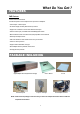
TABLE OF CONTENTS What Do You Get ? • FEATURES -------------------------------------------------------------------------------------- 1 • PACKAGE INCLUDING ---------------------------------------------------------------------- 1 Before Operation • INSTALLATION GUIDE ---------------------------------------------------------------------- 2 • FRONT PANEL ---------------------------------------------------------------------------------- 3 • BACK PANEL ----------------------------------------------------
TABLE OF CONTENTS Advanced Operation • OPERATION OPTIONS ----------------------------------------------------------------------- 43 • KEY LOCK ---------------------------------------------------------------------------------------- 44 • TROUBLE SHOOTING-------------------------------------------------------------------------- 44 • SPECIFICATIONS ------------------------------------------------------------------------------- 45 Appendix • APPENDIX #1 – INSTALL HDD--------------------------------------------
What Do You Get ? FEATURES DMR Features •Remote control via the Internet •Wavelet Compression Format replaces Time-Lapse VCR + Multiplexer • 4 Audio inputs / 2 Audio outputs • On Screen Display and RTC (Real time clock) Function • Support from 4 channels to 7/9/10/13/16 channels video inputs • Picture-In-Picture (PIP) is available in live and DMR playback modes • Motion detection function and 4 level video quality adjustable on each channel • Alarm Input & Output Function • Video loss detected on each cha
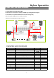
INSTALLATION GUIDE Before Operation 1. Connect cameras and monitor with the DMR. 2. Shown below is one example for connecting the DMR to your existing Observation System. 3. Install HDDs (The compatible HDD Brands are listed in the following table.) Please refer to page.46 Appendix #1 for installation instructions. The HDDs must be installed before the DMR is turned on.
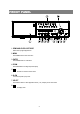
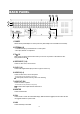
FRONT PANEL 1 3 2 5 4 7 6 9 8 11 10 13 12 15 14 Up 16 Left MENU SELECT ENTER ZOOM SLOW HDD HDD ALARM TIMER P LAY REC Fu ll 1. REMOVABLE HDD CARTRIDGE Please refer to page.46 Appendix #1. 2. MENU Press MENU button to enter main menu. 3. ENTER Press ENTER button for confirmation. 4. ZOOM Press ZOOM button to enlarge the picture display. 5. Press PIP button for Picture in Picture screen. 6. SLOW To slow down speed of play mode. 7.
9. 7, 9, 10, 13 channels display mode 10. 16 channels display mode 11. LED LIGHT The LED Light is ON under the following conditions. •HDD : HDD is activated •HDD Full : HDD is full •ALARM : If you want to turn off the ALARM LED light, please refer to page.13 and set the Camera / ALARM item as OFF. (all of the cameras should be set as OFF.) •TIMER : When Timer is set as Enabled •PLAY : On Play mode •REC : On Recording mode 12. CAMERA (1-16) Press the Camera Select (1-16) to select specified camera. 13.
BACK PANEL 8 6 7 5 4 1 2 3 10 9 1. POWER Please use the provided adaptor to connect power cord (Other adaptors are not suitable for this machine). 2. EXTERNAL I/O •Controlled remotely by an external device or control system. •Alarm input, external I / O explanation. 3. 75Ω / HI When using Loop function, please switch to HI. If you don’t use Loop function or disconnect the video input, please set it as 75Ω. 4. VIDEO INPUT (1-16) Connect to video source, such as camera. 5.
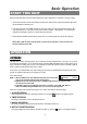
Basic Operation START THIS UNIT Before using the DMR, please have the HDDs installed ready. (refer to Appendix #1 for installation or removal of HDDs). 1. Connect the AC Power Cord with Power Adapter and plug into an electrical outlet. The Red LED indicator light will be ON and the DMR is in Standby mode. 2. Press the Power button. The POWER LED will turn from red to orange, and other red LED indicators will turn ON.
PLAY Press “ PLAY ” button, the DMR will show the last recording. 1. FAST FORWARD (F.F. ) & FAST REWIND (F.R.) You can increase speed for Fast Forward and Rewind on the DMR. In the Play mode, press ” ►► ” once to get 2X speed forward and press twice to get 4X speed,… and the maximum speed can reach 32X. Press ”◄◄ ” once to get 1X speed rewind and press twice to get 2X speed, … and the maximum speed can reach 32X. 2. SLOW FORWARD (S.F.) & SLOW REWIND (S.R.
Detailed Menu Setup MENU M ENU SEAR CH TIM ER R E CO RD C A M ERA SY STEM EVENT NETWORK LA ST R E CO RD D AY H D D OV ERW R ITE TITLE A U DIO INPUT SEVER I P FU LL LIST STA RT R E C O R D IPS D W ELL IN T AU D IBLE ALA RM GATEWAY A LA R M LIST EN D R E C OR D Q U ALITY B rightness / C ontrast / C olor EX T A U D IBL E A LA RM NET MASK M O TIO N LIST Q U A LITY A LA R M R E C IPS A LA RM M O TION A U DIB L E A LA RM D NS TIM E SEA R CH IPS A LA RM R EC Q UA LITY R E CO RD
ACCESS MENU The Menu allows you to configure your DMR settings. Please follow the steps below to access the Menu : Password: 0000 Press the Menu button. The password screen will appear: NOTE : The default Password is 0000. Press the Enter button to access the Menu. To key-in the Password, press the “Right” and “Left” buttons to move between numbers, and use the “Up” and “Down” buttons to input the number. Press the ENTER button once the correct Password is entered. The MENU options screen will appear.
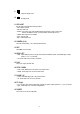
MENU OPTIONS SYSTEM 1. AUDIO INPUT To choose one of 4 channels to record. (can only select 1 during operation for recording) 2. INT AUDIBLE ALARM To set the INTERNAL AUDIBLE ALARM. It will be trigged by event occurrence when the setting is ON. 3. EXT AUDIBLE ALARM (MENU) SEARCH TIMER RECORD CAMERA ►SYSTEM EVENT NETWORK To set the EXTERNAL AUDIBLE ALARM. It will be trigged by event occurrence when the setting is ON. 4. MOTION AUDIBLE ALARM To set the MOTION AUDIBLE ALARM.
11. NEW PASSWORD : XXXX (Default password : 0000) To set the new password. 12. CLEAR HDD Delete all the contents of your HDD. When you choose “YES” on this option, you will be prompted with the question shown : Press “►” to clear HDD or press ”◄” not to clear HDD. ALL DATA IN HDD 13. SYSTEM RESET WILL BE CLEARED ARE YOU SURE? Reset the system to book to the factory default settings. (◄ : NO ► : YES ) SEARCH Press ”ENTER” to confirm SEARCH setup, and the screen will show the following options.
TIMER 1. DAY Select the day, or days of the week (Mon–Fri / Sat-Sun / Daily) that you wish to schedule the DMR to auto recording. NOTE : 1.Special Date could be changed by “Enter”, “Up” and “Down” buttons. 2. If you have selected the specific date and recording timer set from that specific day to a new day, then the Recording Timer Schedule will be set as a whole week. For specific date of Recording Timer Schedule, it is not recommended to set End Time over 23:59.
RECORD 1. HDD OVERWRITE Select “YES” to overwrite previous recording video in HDD. NOTE : When the HDD is full under O/W Recording mode, previous recorded files may be overwritten without further warning notices. (MENU) SEARCH TIMER ► RECORD CAMERA SYSTEM EVENT NETWORK 2. RECORDING IPS Select the images per second of recording. The options are as following : NTSC-25A、15、8、4、2、1 PAL-18A、12、6、3、2、1 NOTE : “A” means “Record with Audio ”. 3.
NETWORK Press the “▲” “▼” ”◄” “►” buttons to move the cursor. Press the “+” “-” buttons to change the digit. Press the “MENU” button to confirm the changes/ to exit the menu. Set IP ADDRESS, GATEWAY, NET MASK, DNS and PORT. Choose YES in RESET DEFAULT will go back to default value of NETWORK. (NETWORK) SERVER IP 192.168.001.010 GATEWAY 192.168.001.065 NET MASK 255.255.255.000 DNS 168.095.001.
MOTION DETECTION MOTION DETECTION SETUP 1. Press “ MENU “ to enter the menu set up, then “ Down ” to CAMERA setup. 2. Press “ENTER” twice to enter the Motion Detection Setup. 3. Each screen displays the current camera picture overlaid with the motion targets (as Figure 1). You can push the button “ Left ” or “ Right ”, ” Up ” or “ Down ” to adjust motion detection in ON or OFF. 4. The targets on each motion setup can be turned to ON or OFF individually.
Figure 1-1 MOTION DETECTION SETUP — 1~15 Figure 1 MOTION DETECTION SETUP 1 2 3 4 5 6 7 8 9 10 11 12 13 14 1 15 2 3 4 5 6 7 -- -- -- -- -- -- -- -- -- -- -- -- -- 2 3 4 5 6 7 8 9 10 11 12 -- -- -- -- -- -- -- 13 14 15 1 2 3 4 5 6 -- -- -- -- -- -- -- 7 11 12 13 14 15 -- -- -- -- -- -- -- -- 8 9 10 11 12 13 14 15 032 032 -- 10 Figure 1-3 MOTION DETECTION SETUP-- ALL Figure 1-2 MOTION DETECTION SETUP-- LINE 1 9 0
Network Setting Guide HARDWARE CONNECTION AT DMR SIDE Direct Connect with PC PC CAMERA MONITOR Remote Connect Via Internet CAMERA PC MONITOR 17
STATIC IP SETTING STEP1: Software installation 1.Put the attached CD into a CD-ROM and it will start to install the application program on Windows PC. 2. Press “Next”. 3.Choose destination location and press “Next”.
4.Set program shortcuts setting and press “Next”. 5.Press “Next” to copy files 6.After the installation, there are 6 files and 1 folder in your assigned path (file folder) as below.
Step2 : Static IP setting In DMR MENU / NETWORK set IP ADDRESS, GATEWAY, NET MASK, DNS and WEB PORT which are provided from your local ISP ( internet service provider ). (MENU) SEARCH TIMER RECORD CAMERA SYSTEM EVENT ► NETWORK For example (NETWORK) SERVER IP 61.66.138.74 61.66.138.254 GATEWAY 255.255.255.000 NET MASK 168.095.001.001 DNS WEB PORT 00080 RESET DEFAULT NO After all network settings are finished, please connect DMR to internet.
Step3 : Connect PC and DMR via the internet Click twice and enter your User name, Password (Note : If you never change the “Account” before, the default user name and password are both “admin”) and Server IP which you have set to DMR in step 2. Then click OK to connect.
DYNAMIC IP SETTING Step1 : Software installation 1.Put the attached CD into a CD-ROM and it will start to install the application program on Windows PC. 2. Press “Next”. 3.Choose destination location and press “Next”.
4.Set program shortcuts setting and press “Next”. 5.Press “Next” to begin copying files 6.After the installation, there are 6 files and 1 folder in your assigned path (file folder) as below.
Step2 : DDNS apply 1. Click on free site “http://www.dyndns.org” ( please look at the example below, you can also apply DDNS in other DDNS web page) and “ACCOUNT” 2.
3. Register the information and click on “Create Account” 4.After registering your account, you will receive an e-mail, which contains instructions to activate your account. If you do not follow these directions within 48 hours, you will need to re-register your account. 5.Login your account.
6.Click on“Account” and “Add Host” 7 Users can set up their own DDNS HOST. For example, the user’s applied Host name is “TEST”. And then press “Add Host” to finish the setting. (NOTE : Some routers don’t support some DDNS HOST) TEST Step3 : Login router NOTE : The following settings are different from router to router. Please read the instruction of your router thoroughly. 1.
2. Network setting for PC. (The instruction is based on Win XP O/S. If your O/S is Win 2000 or Win 2003, the setup procedure is similar to that of Win XP O/S.) Click 3.
4.Click on “INTERNET PROTOCAL (TCP/IP)” , then select “Properties” to setup 5.Choose “Obtain an IP address automatically” . . . . . . . . . 6.
7. In the setting window, type “ ipconfig” to find out router’s gateway(e.q. 192.168.1.1) 8. Close the window in the above step. Enter the IP address ( router’s gateway : 192.168.1.1 ) to log in to the router from internet explore. And then enter the login web page and key in the router’s user name and password.
Step4 : Router setting NOTE : In the router setting, we have four steps as follows. 1. Dial setting 2. DHCP setting 3. Virtual server setting 4. DDNS setting (◇ The following settings will differ from router to router. Please refer to the user’s manual of router) 1.Press “INTERNER PORT” and choose your WAN type (e.q. PPPoE), and then enter your “User Name” and “Password” of dialing up to dynamic IP. Press save after you finish the set up. TEST 2.
3. In “ADVANCED SETUP / Virtual Server”. Choose “By Port” and set “Port Number” to 80 for DMR. And set “Local Server IP Address” to 192.168.1.10. Press add after you finish the set up. 4. In “ADVANCED SETUP / Dynamic DNS”. Key in the “DNS Account”, “User Name” and “Password” that you applied in step 3. Press save after you finish the set up.
Step 5 : IP setting In DMR MENU / NETWORK set SERVER IP, GATEWAY, NET MASK, DNS and WEB PORT. (MENU) SEARCH TIMER RECORD CAMERA SYSTEM EVENT ► NETWORK For example (NETWORK) SERVER IP 192.168.001.010 GATEWAY 192.168.001.065 NET MASK 255.255.255.000 168.095.001.
Step7 : Connect to DMR via internet 1. Change PC network setting to the original setting and link PC to the internet. 2. Click twice and enter your User name, Password and host (Note : The default User Name and Password are both “admin”). Then click OK to connect. Backup Program Play the last record file admin test.dydns.org NOTE: There are two ways to get the software, one is via attached CD, and the other is via Video Web Server.(Refer to P.
SOFTWARE OPERATION AT CLIENT SIDE Follow the steps for connection at your client site (remote site). (e.g. If you set up the server at your office with one static IP, you can remotely proceed to watch the video anywhere with a networked computer.) Step 1:Click twice to enter Login setup (please refer to “software installation”) Step 2:Key in “User Name” and “ Password”. Click “OK” to establish the connection.
INTRODUCTION OF BASIC OPERATION A. Video Web Server control panel 3 2 4 5 6 7 1 1. Image transmission rate per second 2. Data transmission rate 3. Connection/Disconnection 4. Resolution : D1、CIF 5. Image quality : High、Middle、Low 6. Image adjusting : Brightness/ Contrast/ Saturation 7. Snapshot : press this button, the image will be automatically saved in the PC. 8. Record : press this button, the recording file will be saved in the PC automatically. 9. System Config 10.
B. Digital device control panel 7 1 2 3 4 6 1. CH1-16, 2. 4cut, 7cut, 9cut, 10cut, 13cut,16cut, PIP 3. Zoom, Select, Lock, Record 4. Stop, Rewind, Fast Forward, Pause, Slow, Play 5. Menu(Exit), Left, Right, Up, Down 6. Enter 7. TURBO uNOTE: After you press the record icon, there will be a recording file in the path that you have set.Each recording file can be save up to 6000 frames. The recording file will be assigned to the second File if it is more than 6000 frames.
PLAYBACK OPERATION Please find a recording file in the PC and click twice on it to playback. 1 2 3 4 5 6 7 8 9 10 11 12 13 20% CH1 2004/12/15 09:49:38 2004-DEC-15 [WED] 09:49:33 Ad 001.4 GB O/W NTSC_CIF 219.84.21.166 1. On Screen Display 8. OSD show / hide 2. Snapshot 9. Config setting (Path of snapshot, text color, progress 3. Stop color, channel color) 4. Pause 10. Open Last File 5. Slow (1/2X, 1/4X, 1/8X, 1/16X, 1/32X) 11. Open Next File 6. PLAY 12. Duration time / Status 7.
ADVANCED SETTING Click “System Config” for advanced setting. NOTE : Apply-After changing all setting, press “apply” to refresh the data. Reboot-Press this button to restart the server. SYSTEM CONFIG ACCOUNT Set up the user’s account( Max 10 accounts) , password and authority ( Max 6 accounts on line at the same time) . 1.User’s level: SUPERVISOR-control all the functions HIGH LEVEL-control advanced functions NORMAL -control basic functions only GUEST LEVEL –watch the image only 2.
MAIL When the alarm is triggered, the video server program will capture the instant picture and e-mail the captured image to the assigned recipients. 1.You can get all the data from the ISP company or by mailing to the server supplier.(POP3/SMTP server) 2.You should set the mail list which you want to send to when the alarm is triggered. 3.If it is not necessary for you to verify password and user’s name, please choose Verify as “No”.
TOOLBOX Upgrade the firmware and get the online users’ information. NOTE :Do not reboot the DMR while it is upgrading the firmware. 1.Firmware Version : The current firmware version. You can click on “Find” button to get the latest firmware from PC and press “Upgrade Firmware” to upgrade it. 2.Turbo Step:Activate the turbo button when you would like to shift the selections more quickly by jumping 6 selections at a time. Online User The information of online user.
CONNECT VIDEO WEB SERVER VIA IE BROWSER You can also connect Video Web Server via browser. This function is suitable in both WIN 2000 and WIN XP ( WIN XP is preferable to WIN 2000) Step 1:Enter IP address that you want to connect.(example) 219.84.21.166 Step 2:Enter your Username and Password to login Video Web Server.
Step 3:After you login, you will see as below. (example) 2 3 4 5 6 7 8 9 1 10 11 12 13 14 15 1.Image transmission rate per second 9.Quality switching button 2.Data transmission rate 10.Menu, Left, Right, Up, Down, Exit 3.Video Channel 11.Lock, Enter, Zoom, Search, Select. 4. Resolution :D1、CIF 12.Stop, Play, Record, Rew, Fast, Pause, Slow 5.Image quality : High、Middle、Low 13.Camera 6.Number of online users 14.4cut, 7cut, 9cut, 10cut, 13cut, 16cut, Pip 7.Channel switching button 15.
Advanced Operation OPERATION OPTIONS SELECT This device allows user to get the ideal view size. àPress , , button to make different view size. àPress “ Select ” then “ Left ” or “ Right ” button to locate the desired position. àPress “ Camera Select (1-16) “ to select the appointed camera. àPress “ Menu “ to exit. PICTURE IN PICTURE (PIP) Press PIP button to enter PIP display screen. The PIP format displays a full screen “background” picture with a 1 / 16 size screen “insert”.
KEY LOCK For further security, you can “Lock” all buttons on your DMR. Locking disables the buttons and prevents other people from using the system. Press ENTER and MENU at the same time to enable Key Lock. Press ENTER and MENU at the same time and key in password (Default : 0000), then press “ENTER“ to disable Key Lock. TROUBLE SHOOTING RS232 REMOTE PROTOCOL When malfunction occurs with DMR, it may be not serious and can be corrected easily.
SPECIFICATIONS TROUBLE SHOOTING Video format Network Interface Protocals Trigger & Action Hard disk storage Record mode Camera Input Signal Camera Loop Back Main Monitor Output Call Monitor Output Audio input Audio output Motion Detect Area Motion Detect Sensitivity Video Loss Detection Refresh Rate Recording Rate Dwell Time Picture in Picture Key Lock Picture Zoom Camera Title Video Adjustable Alarm Input Alarm Output Time Display Format Power Source Power Consumption Operation Temperature NTSC/EIA or PAL
APPENDIX #1 – INSTALL HDD Please follow the next steps carefully in order to ensure correct installation. The compartment located on the front panel of the DMR is the removable Cartridge Casing in which you insert the HDD. The various parts of the Cartridge Casing are labeled for your reference. 1.Remove the Cartridge Case from the DMR Keyhole Cartridge Casing LED indicator lights Handle 2.
4. Secure the HDD in the Casing (optional) Use the supplied screws and tighten them, and positioning the HDD into place. 5. Slide the top Cover over the Cartridge Casing Slide the Cover forward over the Cartridge Case. Ensure it is secured in place over the release latch. 6.Reinsert the Cartridge Casing into the DMR Fully insert the Cartridge Case into the DMR. 7. Lock the Cabinet Lock the cabinet by turning the key clockwise.
APPENDIX #2 – RACK MOUNT Screws and brackets for rack mounting applications can be purchased as an optional accessory.
APPENDIX #3 – RECORDING SPEED The Record Time is different based on Record Speed and Record Quality. Please refer to following table. NTSC SYSTEM PAL SYSTEM Note: Above data is from actual test data obtained from recording normal TV program.
APPENDIX #4 – PIN CONFIGURATIONS 25 pin com port DMR EXTERNAL ALAM NO EXTERNAL ALARM COM PIN OFF ALARM INPUT 9 ALARM INPUT 10 ALARM INPUT 11 ALARM INPUT 12 ALARM INPUT 13 ALARM INPUT 14 ALARM INPUT 15 ALARM INPUT 16 ALARM INPUT 1 ALARM INPUT 2 ALARM INPUT 3 ALARM INPUT 4 ALARM INPUT 5 ALARM INPUT 6 ALARM INPUT 7 ALARM INPUT 8 PIN OFF GND GND GROUND PIN 1 ALARM INPUT To connect wire from ALARM INPUT ( PIN 2 -- 9 ; PIN 15-22) to GND ( PIN 1 ) connector, DMR will start recording and buzzer will be on.