SSA-0412 USER GUIDE 4 Channel MPEG-4 Digital Video Recorder Ver. 2.1 About this user guide Before installing and using this unit, please read this user guide carefully. Be sure to keep it handy for later reference. This document contains preliminary information and subject to change without notice.
BEFORE INSTALLATION NOTE: WE DO NOT TAKE ANY RESPONSIBILITY OF DAMAGES RESULTED FROM THE NONSTANDARDIZED GOODS AND FAILURES TO FOLLOW THE MANUAL INSTRUCATIONS. PLEASE ASK FOR HELP TO YOUR LAST SELLER BEFORE DISASSEMBLEING THE SYSTEM FOR REPAIR AND ADD PARTICULAR FUNCTIONS. FCC VERIFICATION Caution: Any changes or modifications in construction of this device which are not expressly approved by the party responsible for compliance could void the user’s authority to operate the equipment.
SAFETY PRECAUTIONS EXPLANATION OF SYMBOLS This symbol is intended to alert the user to the presence of important operation and maintenance (servicing) instructions in the literature accompanying the appliance. This symbol is intended to alert the user to the presence of unprotected “dangerous voltage” within the product’s enclosure that may be strong enough to cause a risk of electric shock persons. CAUTIONS THIS PRODUCT HAS MULTIPLE-RATED VOLTAGES (110V AND 220V).
WARNINGS The product should be installed by a trained professional. The DVR should be powered off when connecting camera, audio, or sensor cables. The manufacturer is not responsible for any damages caused by improper use of the product or failure to follow instructions for the product. The manufacturer is not responsible for any problems caused by or resulting from the user physically opening the DVR for examination or attempting to fix the unit.
RACK MOUNT INSTRUCTIONS The following or similar rack-mount instructions are included with the installation instructions: A) Elevated Operating Ambient - If installed in a closed or multi-unit rack assembly, the operating ambient temperature of the rack environment may be greater than room ambient. Therefore, consideration should be given to installing the equipment in an environment compatible with the maximum ambient temperature (Tma) specified by the manufacturer.
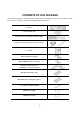
CONTENTS OF DVR PACKAGE The package contains the main unit and its components as specified below. When you purchase the unit, please check to ensure the components specified below are included. DVR Set Client Software CD Remote Controller & Battery1.
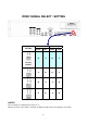
VIDEO SIGNAL SELECT / SETTING SETTING Video mode Video output NTSC PAL BNC VGA O X O X X O O X O X X O X O X O Factory Default NOTICE Do not change the setting when the power is on. When the position of the switch is changed, the DVR should be rebooted to apply the new setting.
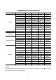
COMPATIBLE HDD MODELS COMPANY HITACHI MAXTOR SAMSUNG WESTERN DIGITAL SEAGATE MODEL SIZE RPM BUFFER INTERFACE HDS728080PLAT20 80 GB 7200 RPM 2M E-IDE HDS721680PLAT80 82 GB 7200 RPM 8M E-IDE HDT722516DLAT80 160 GB 7200 RPM 8M E-IDE HDT722516DLAT80 164 GB 7200 RPM 8M E-IDE HDS722525VLAT80 250 GB 7200 RPM 8M E-IDE HDT722525DLAT80 250 GB 7200 RPM 8M E-IDE HDT725025VLAT80 250 GB 7200 RPM 8M E-IDE HDT725032VLAT80 320 GB 7200 RPM 8M E-IDE HDS725050KLAT80 500 GB 72
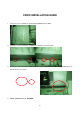
CDRW INSTALLATION GUIDE 1. Open the top cover of DVR set and Install the CDRW inside the DVR. 2. Fasten the screws on both side of CDRW as indicated in red circle below. 3. Connect the IDE CDRW 40pin cable and Power cable to the point on both CDRW and Main board as indicated in red circle below. 4.
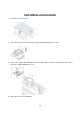
HDD INSTALLATION GUIDE 1. Unfasten the cover of the unit. 2. Fix the bracket to the hard disk using the supplied HDD mounting bracket screws. 3. Connect the supplied IDE HDD 80pin cable and Power cable to the hard disk and fix the hard disk to the unit the supplied HDD fixing screws. 4.
SPECIFICATION VIDEO INPUT 4 Composite BNC (NTSC/PAL) – 1.0Vp-p OUTPUT (Selectable) 1 Composite BNC (NTSC/PAL) – 1.0Vp-p 1 VGA (D-sub 15 pin) AUDIO INPUT & OUTPUT 4 Line In (RCA) & 1 Line Out (RCA) ALARM INPUT & OUTPUT 4&1 OS RECORD MULTI TASK RTOS COMPRESSION MPEG-4 VIDEO FORMAT NTSC PAL RESOLUTION 352x240, 704x480 352x288, 704x576 RECORDING MAX. 120fps/4CH(352x240/CH) MAX. 100fps/4CH(352x288/CH) QUALITY MAX. 30fps/4CH(704X480/CH) MAX.
TABLE OF CONTENTS 1. FRONT PANEL AND REMOTE CONTROLLER ........................................................... 15 1-1. Front Panel............................................................................................................................................... 15 1-2. Remote controller.................................................................................................................................... 17 2. REAR PANEL AND CONNECTIONS...........................................
4. LIVE & SEARCH ........................................................................................................... 41 4-1. LIVE Screen.............................................................................................................................................. 41 4-2. SEARCH screen....................................................................................................................................... 42 4-2-1. TIME LINE Search..........................................
7-6-1. General ............................................................................................................................................... 62 7-6-2. Site...................................................................................................................................................... 63 7-6-3. Event................................................................................................................................................... 63 7-6-4. Record ........
1. Front Panel and Remote controller 1-1. Front Panel The following information will help you operate the front panel controls. Figure 1.1 Front panel Table1.1. Indication lamps Name n HDD o RECORD p ALARM q NETWORK r BACKUP Description LED light is on when the system is accessing the hard disk. LED light is on when the system is recording video data. LED light is on when alarm sensor(s) is/are triggered or motion is detected. LED light is on when client is connected to the system through the network.
playback mode. Press to rewind the footage at 1x, 2x, 4x, and 8x speed in playback mode. Press to select audio mode such as SINGLE, MIX and MUTE. MUTE- All of 4 channels. SINGLE- Highlighted channel only. MIX- All of 4 channels. Jump/Step backward. In playback mode, the playback position moves 60 seconds backward. Press to enable/disable ALARM operation. Jump/Step forward. In playback mode, the playback position moves 60 seconds forward.
1-2.
2. Rear Panel and Connections Figure 2.1. Rear Panel Table 2.1. Rear panel connections Connection n VIDEO IN o AUDIO IN p AUDIO OUT q VIDEO OUT r RS-232 s VGA t ETHERNET u RS-485/422 DESCRIPTION Four connectors for video input. Connect camera output to Video-in (NTSC/PAL) Four connectors for audio input. One connector for audio output.
Figure 2.2. Rear Panel Connections 1 3 2 4 SENSOR OUT ALARM Sensor (-) (-) (+) (+) Dried Contact +12VDC Adapter Figure 2.3. Sensor input / Alarm output connections SENSOR INPUT: Connect two signal lines of sensor (infrared rays sensor, heat perception sensor, magnetic sensor) to the desired sensor number. (You can set the type-NC or NO- of sensor at “Setup” mode). ALARM OUTPUT: Use this at 30V/300mA or less operating voltage and current.
3. Setting up the DVR The following sections detail the initial setup of the DVR 3-1. SETUP - Main Screen When you press the SETUP button, the DVR will ask for a password (Figure 3.1.1). The default password is 1111, which can be entered by pressing the up button ( ) 4 times and then pressing the SEL button. We recommend you protect the system by assigning a new password immediately. The procedure for assigning a password is found in section 3.4 SYSTEM.
` Figure 3.1.2. SETUP Main screen Table 3.1.1.
SET DATE & TIME – DAY LIGHT SAVING – USA, EU, OTHERS SEND MAIL – MAIL ADDRESS, M-SERVER NAME, RETURN MAIL ADDRESS P/WORD ADMIN PASSWORD NETWORK PASSWORD NETWORK PORT CLIENT ACCESS BANDWIDTH SAVING NETWORK TYPE – LAN, DHCP, ADSL DDNS – DDNS NAME CONFIG SAVE SETUP TO A USB LOAD SETUP FROM A USB LOAD DEFAULT 3-2. Setup – DISPLAY Mode Set values for live display. Navigate through the menu items by pressing the UP/DOWN buttons. The value of the menu item may be changed by pressing the LEFT/RIGHT buttons.
CONTRAST Change the contrast value for the specified channel HUE Change the hue value for the specified channel SATURATION Change the saturation value for the specified channel 3-3. Setup – RECORD Mode Set the values for recording video. Navigate through menu items by pressing the UP/DOWN buttons. User can change the value of the menu item by pressing the LEFT/RIGHT buttons. Figure 3.3.1. RECORD mode setup screen Table 3.3.1.
MOTION- Set the motion sensitivity for the specified channel. SENSITIVITY Control the motion sensitivity from 1 to 9. SENSOR TYPE Set the type of sensor for the specified channel from none, N/O (normal open), and N/C (normal closed). PRE RECORD Enable/disable pre-event recording. Pre-event recording time is 5 seconds and only intra-frames are recorded for pre-event recording.
3-3-2 Motion Zones By selecting Partial Zone in the Motion Zone menu, users can set-up the motion sensing zones in the screen shown in figure 3.3.2. Move around each rectangular zone using 4 direction key buttons and press SEL button to include the rectangular region as part of the motion sensing zone. The rectangular blocks included as part of the motion zone are indicated by changing the color of the blocks.
SYMBOL MEANING C Continuous recording mode M Motion detection triggered recording mode S Sensor triggered recording mode Figure 3.3.3. SCHEDULE Recording setup screen 3-4. Setup – Device Mode To set values for device, use the UP and DOWN controls to navigate through the menu items. Change the value of the menu item using the LEFT and RIGHT controls.
Figure 3.4.1. Device mode setup screen Table 3.4.1. Menu items in Device Setup screen Description Set the PTZ camera speed, number, type and ID. Select specified channel for motion zone and sensor/alarm setup. Select Full Zone or Partial Zone for motion sensing. Set the motion sensitivity for the specified channel. Control the motion sensitivity from 1 to 9. Set the type of sensor for the specified channel. Options are: None, SENSOR TYPE N/O (normal open), and N/C (normal closed). Select alarm from 1 to 4.
The following options are available on the PTZ control screen. CHANNEL (channel number that the PTZ is connected to) NAME (protocol type) SPEED (19200, 14400, 9600, 4800, 2400) ID (0-63) 3-4-2. Motion Zone Setup When you select Partial Zone in the Motion Zone menu, you can set-up the motion sensing zones in the screen. To move around each rectangular zone, use the arrow controls. Press the SEL button on each rectangular zone you want to include as part of the motion sensing zone.
Figure 3.5.1. STORAGE setup screen Table 3.5.1. Menu items in STORAGE Setup screen Description When enabled, the DVR will continue recording and overwrite the oldest existing recorded data once the hard drive is full. When disabled, recording will stop once the hard drive is full. Format the hard drive. Use the UP and DOWN arrow buttons to DISK FORMAT select ON, then press SEL. You then have the option to YES or NO. Caution All recorder data will be lost.
Figure 3.6.1. SYSTEM Setup Screen Item DVR ID DESCRIPTION LANGUAGE DATE FORMAT SET DATE&TIME Table 3.6.1. Menu items in SYSTEM Setup screen Description Set the name of the DVR. Press the SEL button, use the LEFT and RIGHT or UP and DOWN arrow controls to navigate through the position for each alphanumeric character and Press SEL to apply the selected character. And Press OK to confirm the name.
SEND EMAIL UP and DOWN arrow controls to change the value of month, week, day and hour. CAUTION: -Do not set the start time to 23:00 for DLS. -DLS can’t be applied, if the date of BEGIN and END is same. Enable/disable SEND EMAIL function. IP NOTIFICATION: Enable/disable sending daily e-mail reports on the status of your DVR. EVENT ALARM: Enable/disable sending e-mail reports when event alarm occurs. MAIL ADDRESS: Enter the appropriate email address to enable sending daily e-mail reports.
Figure 3.6.3.DESCRIPTION Screen Figure 3.6.4.SET DATE & TIME Setup Screen Figure 3.6.5.DAYLIGHT SAVING Setup Screen Figure 3.6.6.
3-7. Setup – PASSWORD Mode Use the LEFT or RIGHT and UP and DOWN arrow controls to set the password. Figure 3.7.1. PASSWORD setup screen Table 3.7.1. Menu Items in PASSWRORD Setup Screen Item ADMIN PASSWORD NETWORK PASSWORD Description Set the administrator password. After selecting this menu item you will be promoted for your current password and then the new password. Follow the prompts to change and confirm the new password. The default password is 1111.
when connecting to this DVR through the client software program. After selecting this menu item you will be prompted for your current password (the default password is 1111) and then the new password. Follow the prompts to change and confirm the new password. Use the arrow controls to change the password as described in ADMIN PASSWORD above. 3-8. Setup – Network Mode Set up your network parameters on the Network Setup screen. Figure 3.8.1. NETWORK setup screen Table 3.8.1.
Subnet Mask: Register Subnet Mask that is assigned for DVR. DDNS Enable/disable using domain name address through DDNS server. “ON” mode, DDNS server name appears for domain registration. The DDNS sever name is ns.standalone4ch.com. CAUTION: Do not change this sever name. If this is changed, the DDNS service cannot be used. Registration Check the MAC address of DVR from Setup>System>Description. Please contact a distributor or an installer to register your DVR on a DDNS Server.
3-8-2. Network Types 3-8-2-1. LAN 1. Regarding to the use of fixed IP please ask your network administrator if you do not have this information. 2. When DVR is installed in IP sharer that is connected with ADSL, a user can assign fixed IP to DVR from IP sharer itself using “DMZ” function out of such sharer. Input IP set in DMZ on “IP” field and Gateway of ADSL modem on “Gateway” field. Similarly, for Subnet Mask, DNS address, input relevant values in IP sharer. Figure 3.8.2.
GATEWAY SUBNET MASK DNS The IP address of the Gateway The subnet mask for the LAN The address for the DNS server 3-8-2-2. DHCP An IP address is automatically assigned by the DHCP server, which automatically assigns IP address and other parameters to new devices. When ADSL or other network being used adopts variable IP method, not fixed IP. This option is used as a way to automatically get IP address. Figure 3.8.3. Network setup screen - DHCP 3-8-2-3.
Item ID PASSWORD Description The user ID for the ADSL connection The password for the ADSL connection 3-8-3.
LOAD CONFIG LOAD DEFAULT User can upload the configuration of DVR to another DVR using the USB Memory stick. Put the USB stick on the front panel and press SEL to start the loading process. Select ON to reset the system to the default settings. (Password, date format, DLS, Network setting, and HDD Overwrite will not be included.
LOAD FACTORY DEFAULT Select ON to reset the system to the factory default settings. 3-9-1.Saving Setup To preserve the setup values that you have selected, select YES. Figure 3.9.2.
4. LIVE & SEARCH 4-1. LIVE Screen In the LIVE screen, video inputs from the cameras are displayed on the configuration of the live setup. Figure 4.1.1 shows the layout of the live screen. Various indicators showing the status of the DVR are shown as OSD symbols. Refer to Table 4.1.1 for the meanings of the indicators. Figure 4.1.1. LIVE display screen Table 4.1.1. Indicator ICONS in LIVE screen INDICATOR DESCRIPTION Continuous recording in progress. Manual recording in progress.
Indicates that alarm output is activated. Indicates that lock function for a remote control is set. Alarm indicator. When there is an alarm (sensor or motion alarm) in the video channel, this icon will be highlighted bright red. Indicates that a network client is connected to the DVR. Indicates that sequencing mode is enabled. Table 4.1.2. Button functions in LIVE screen BUTTON DESCRIPTION Select channel to be displayed in full screen mode. Switch between full screen and quad display mode.
Figure 4.2.1. Password screen Figure 4.2.2. SEARCH screen 4-2-1. TIME LINE Search The TIME-LINE SEARCH screen is used to find the stored video by using the time line bar. (Figure 4.2.3) 1. Select the date of the video to begin searching by using the LEFT or RIGHT button to navigate through the day. 2. Once you have selected the date, press the SEL button to move to the TIME LINE SEARCH screen. 3. Use the LEFT or RIGHT button to select a time zone on the 24hours time table.
Figure 4.2.3. TIME LINE SEARCH screen 4-2-2. EVENT Search The EVENT SEARCH screen is used to find the stored video. 3 categories of search filters can be applied: DATE, CHANNEL, and TYPE. Use the SEL button to move down the categories and use the UP button to move up the categories. The ESC button will return user to the live screen. Searching for an event: 1. Select the date of the video to begin searching, Use the LEFT or RIGHT button to navigate through the day.
R(Manual), C(Continuous). 6. Once you have selected the type of recording to search for, press the SEL button to produce a list of instances that fit the search criteria. Figure 4.2.4. EVENT SEARCH screen Figure 4.2.5. EVENT SEARCH LIST screen 7. Use the UP and DOWN button to scroll through the onscreen listings. 8. Use the LEFT and RIGHT buttons to display events that happened previous to or after the current selection. 9.
Figure 4.2.6. GO TO SEARCH screen 4-2-4. GO FIRST You can access to the first data which has been recorded into USB Stick or CD media by pressing this menu. 4-2-5. GO LAST You can access to the last data which has been recorded into USB Stick or CD media by pressing this menu. 4-2-6. LOG List You can see the log list by selecting this item. Figure 4.2.
Figure 4.2.7. LOG LIST screen 4-2-7. ARCHIVE Search The ARCHIVE SEARCH screen (figure 4.2.8) is used to find the stored video. 1. Select the date on the calendar to begin searching by using the LEFT or RIGHT button. 2. Once you have selected the date, press the SEL button to move to the list of recording data. (figure 4.2.9) 3. Use the UP or DOWN button to scroll through the onscreen listings. 4. Once the desired event has been selected, press the SEL button to see the selected video in paused mode. 5.
Figure 4.2.9. ARCHIVE SEARCH LIST screen 4-3. PTZ operation To operate the PTZF functions, connect the controller to the RS-485 port on the rear panel. (figure 4.3.2) In the PTZ control setting in the SETUP menu (refer to the figure 3.4.5 on page 26), user can select or set the protocol type of the camera which is the same as the one that is installed on the site. If the camera has a specific camera ID, select the camera ID using Left or Right button. The PTZ function button is found on the front panel.
Table 4.3.1. Button functions in PTZF control ITEM DESCRIPTION PAN / TILT Use the UP or DOWN button for TILT and LEFT or RIGHT button for PAN of the selected camera. ZOOM / FOCUS Use the UP or DOWN button for ZOOM in or out and LEFT or RIGHT button for FOCUS near or far of the selected camera. INITIALIZE Initialize the PTZ settings of the selected camera. 1 2 3 4 Figure 4.3.2. RS-422/485 port Table 4.3.2. Description of RS-422/485 port No.
Figure 4.4.1. PLAYBACK mode screen Table 4.4.1. Button functions in PLAYBACK mode BUTTON ESC DESCRIPTION Return to the previous menu screen, search list, or exit menu Press to rewind the footage at 1x, 2x, 4x and 8x speeds. Reverse playback speed is shown as -1x (normal), -2x (2 times normal), -4x (4 times normal) and -8x (8 times normal) at the bottom right of the screen. Jump/Step backward. – The playback position moves 60 seconds backward. PLAY/PAUSE Press to play or pause recorded video.
Switch view between quad and full screen mode displaying highlighted channel. BACKUP Press the BACKUP button to archive the still image or video clip into USB stick or CD media. 5. Archiving Video You can archive a still image or video clip to a USB stick or CD media and hard drive. 5-1. Capturing and transferring still images or video onto USB or CD media.
Figure 5.1.2. MEDIA Select Screen VIDEO ARCHIVE Video can be captured and archived onto the USB stick or CD media or hard drive while playing back recorded video. In playback mode, press the BACKUP button to launch the archiving function. When you press BACKUP button, the DVR will ask whether to archive a Still Image or Video clip as Figure 5.1.3. Figure 5.1.3. ARCHIVE Mode Screen If user selects VIDEO, the DVR will ask for the setting of the archiving duration as Figure. 5.1.4.
Figure 5.1.4. ARCHIVING DURATION Setting Screen Then DVR will ask which media you will take for archiving as Figure. 5.1.2. Once you select the media, the system will start to archive the data to the selected media. Figure 5.1.5. ARCHIVE Ongoing Screen The DVR will convert the corresponding portion of the video into an AVI file. 5-2. Transferring still images or video from the ARCHIVE list The stored data onto hard drive will be found in the ARCHIVE list in SEARCH menu. (Figure 5.2.
the current selection. 5. Once the desired event has been selected, press SEL to view the still image or the first frame of the selected video. 6. Press the BACKUP button to launch the archiving function in playback mode. 7. See the Chapter 5-1 for archiving procedure. Figure 5.2.1. SEARCH menu screen Figure 5.2.2.
Figure 5.2.3. ARCHIVE LIST Screen Figure 5.2.4. VIDEO TYPE Select Screen In the case of video, the system will change the video and audio into AVI format while transferring the video file into the storage device. NOTICE During the backup, the DVR will operate in Simplex 5-3. Playing AVI video from USB memory stick or PC through Network S/W If there is proper CODEC installed in PC, it is possible that the backup data can not be play-backed.
6.
7. Network – By an exclusive viewer The DVR provides a live remote monitoring feature. Remote monitoring requires installation of a software client program on your PC. NOTICE In a high bandwidth network, a maximum of four users can access one DVR simultaneously. In a low bandwidth network it is recommended that only one user access the DVR at a time. For remote viewing, the frame rate is limited to 1 frame/sec when there is no recording operation in the DVR.
7-2. Minimum PC requirements PC Specification Minimum Requirement Recommended CPU Intel Pentium Ⅲ Intel Pentium Ⅳ 500Mhz 2Ghz Memory 128MB 256MB VGA 16MB 64MB Resolution 1024x768 1024x768 Disk space 10MB 10MB OS Windows 2000 Windows 2000, Professional, XP Vista Network 10/100Base T 10/100Base T Others Direct X 8.1 Direct X 9.0 or Higher Before installing the program, check the PC specifications.
7-4. Live viewer When installation is complete, double click the icon on your desktop to start the program. Figure 7.4.1. Main user interface Table 7.4.1. Main controls in Live NO Button Description 1 DATE & TIME Displays the current date and time. 2 CONNECT Click this icon to connect to the DVR 3 SEARCH Click this icon to search for recorded video. 4 LOCK/ UNLOCK Click this icon to lock/unlock all operations of the client software.
5 PAN/TILT Use these buttons to control the PAN/TILT features on the remote camera. 6 ZOOM/ FOCUS Use these buttons to control the ZOOM/ FOCUS features on the remote camera. 7 CAPTURE Click this icon to capture a still image. Once the capture icon is clicked, this pop-up window appears. The still image is captured in either jpeg or bmp file format. 8 PLAY/PAUSE Click this icon to play/pause live video. 9 RECORD Enable or disable recording of live video to local disk.
7-5. Search and Playback Viewer The search window can be accessed by clicking the search icon on the upper right of the main user interface. Figure 7.5.1. Main user interface Table 7.5.1. Main controls in Search No Button Description 1 DATE & TIME Displays the recording time of the data selecte2 0 0 10.02 514.64912T/TT0 1 Tf10.2.
7 8 SEARCH The calendar shows dates with recorded video in a light blue and the CALENDAR selected date in dark blue. TIMELINE BAR The timeline shows recorded data in dark blue on the bar. You can adjust the time-line scale and move it to the time you wish to play back. Click the play icon to display the recorded video. 9 PLAY BUTTONS 10 DISPLAY MODE Click these icons to select display mode. 7-5-1. Backup You can back up recorded video in AVI format from the search viewer. 1.
Security Option: Set a password for security options. Save Path: Specify the location to record the receiving video for Backup and still image for Capture. Automatic reconnection: If a user selects this function, the client S/W will automatically try to connect to the previously connected IP address if the network connection is lost. Display network statistics: If a user selects this function, the client S/W will display network status, Bit rate and Frame rate.
z LOG – Select to save event log into ‘log file’. z ICON – Select to display the event on live video. z EVENT LIST – Select to show the event in the ‘Event List” window of live mode. You can search and check the recorded log data. 7-6-4. Record You can set the recording conditions for Always, Event, or Auto recording. You can also select individual channels or all channels to record.
When you set the recording condition to Event, you can set event for motion or alarm with duration. You can also set each or all channels to record. 7-6-5. Disk You can select which local disk to use and the amount of disk space you want to allow the program to use for recording. You can also choose to overwrite data or stop recording when the maximum amount of disk space is full.
8. Network – By an web-browser viewer The DVR provides a live remote monitoring feature by web-browser viewer. 8-1. Download Web Brower Viewer and Connection 1. User needs to access http://anytimeview.com/ to get a web browser viewer. Then the window will appear as bellow. Click “YES” to download Web Browser Viewer from the server run by the manufacturer. 2. Web Browser Viewer will be downloaded and installed. 3.
8-2. Main Features 8-2-1. Live Figure 8.2.1. Main user interface - Live Table 10.2.1. Main controls in Live No Name Description 1 DATE & TIME Displays the current date and time. 2 CONNECT Click this icon to connect to the DVR 3 SEARCH Click this icon to search for recorded video.
4 LIVE DISPLAY MODE Click these icons to select display mode. 5 PAUSE Click this icon to pause the display screen. 6 CAPTURE Click this icon to capture the image from live display. 7 SETUP Click this icon to control remotely the setting of DVR. 8 PAN/TILT Use these buttons to control the PAN/TILT features on the remote camera. 9 Use these buttons to control the ZOOM/ FOCUS features on the ZOOM/FOCUS remote camera. 10 AUDIO The audio can be turned on or off by clicking the audio icon.
3 LIVE Click this icon to search for recorded video. 4 DISPLAY MODE Click these icons to select display mode. 5 BACKUP Click this icon to pause the display screen. 6 CAPTURE Click this icon to capture the image from playback. 7 SETUP Click this icon to control remotely the setting of DVR. 8 PLAYBACK BUTTONS Use these buttons to control the PAN/TILT features on the remote camera. 9 SEARCH CALENDAR Use these buttons to control the ZOOM/ FOCUS features on the remote camera.
APPENDIX 1. How to register DDNS (Dynamic Domain Name Server) If DVR is installed in network using dynamic IP addressing and user want to access DVR with domain name instead of IP address, user should register DVR and domain name with DDNS. 1-1. Setting of NETWORK Setup menu A. Please go to SETUP>NETWORK. There are three network types such as DHCP, ADSL, and LAN. B. Please select proper network type and set DDNS as ON.
Mac address 00026900A12B Registration No. HDC462135789 NOTE: If there is not registration No. on the system, please contact the distributor or manufacturer. 1-3. Registration at DDNS Please go to http://ddnscenter.com Input MAC Address and Serial Number that you checked from the rear of DVR. And input Domain Name and press [check] to see if Domain name is usable or not. NOTICE You may use alpha and numerical characters as well as hyphens for your Domain name. (i.e.
2. Network access using Domain name If DDNS registration is successful, you can access your DVR via the provided Network Client S/W. A. Run Network Client S/W program and click the “connect” button. B. Enter your domain name instead of IP address in the “IP Address” field. C. Enter the Port No., Protocol and Password in each filed. D. Press OK, then you can access to the remote DVR.