Federal Communications Commission (FCC) Statement This equipment has been tested and found to comply with the limits for a Class B digital device, pursuant to part 15 of the FCC Rules. These limits are designed to provide reasonable protection against harmful interference in a residential installation. This equipment generates, uses and can radiate radio frequency energy and, if not installed and used in accordance with the instructions, way cause harmful interference to radio communications.
Important | Safety instructions, Care and Handling ro 10. . Before starting, take a few minutes to read this manual, read all of these Instructions and save this manual for irate reference. Protect the Disk Ana from extremely high or low temperatures. Let the Disk Array warm (of cool ] to room temperature before using it. Protect the Disk Array from being bumped or dropped. Do not place this product on an unstable cart, stand, or table. It may fall, causing serious damage fo the product. .
Operating Environment | When selecting a suitable working location, please consider : @ Ventilation ® Temperature @ Dust and dirt ® Electromagnetic and Radio Frequency Interference. ® Securely The selected location should provide af least six inches of open space around the Disk Array cabinet for proper air flow, Your Disk Array functions best at normal room temperature. Choose a location free from extreme heat or cod. Warning! The Disk Array's LCD Panel may be damaged by exposure to intense sunlight.
Chapter 1 : Introduction Features General RAID concepts RAID Level 0 RAID Level 1 RAID Level 3 RAID Level 5 summary Comparison of RAID Levels Supported RAID Levels — Tutti-8CSI Format support ee Chapter 2 : Getting Started General Overview Unpacking & Checklist Choosing a place for Disk Array Identifying Parts of Disk Array Front View Rear View Power Source Installing the Hard Disk Drive Host Linkage Ee Power-On & Self-Test LED Display & Function Keys LED Display Function Keys LCD Status Panel Chapter 3 : C
Chapter 1 : " introduction * | This chapter will Introduce you to your new Disk Array's features and provide information on general RAID concept.
Introduction Solid reliability « Automatic failed disk drive detection. « Auto rebuild : when a replacement disk installed (or by using hot spore disk ), Arena provides automatic data rebuild without any commands or functions keyed in, { Transparent fo Host ) Efficient maintenance + An LCD status panel displays a comprehensive readout of the operating status, and the HDD LED indicators on each HDD tray display the Individual HDD status.
Introduction RAID Levels RAID Level 0 : " Disk Striping * High I/O Performance Disk Disk Disk Disk Disks Disk Physical @ Improved YO performance Is the major reason for using RAID level 0. @® No protection is provided against data loss due to member disk failures. A RAID level 0 array by itself is thus an unsuitable storage medium for data that can not easily be reproduced. or for data that must be available for critical system operation.
Introduction RAID Level 1 : " Disk Mirroring * High Data reliability Disk Disk} Disk Disk Disk Disk Physical Optional RAID level 1 provides bath very high data reliability and continued data availability in the event of a failure of an ray member.
Introduction @® The distinctive performance characteristics of RAID Level 3 RAID Level 3 provides excellent performance for data transfer-intensive applications. + RAID level 3 in not well suited for transaction processing or other 1/O request-intensive applications.
Introduction ® RAID level 5 arrays have unique performance characteristics : « The data can be recalculated of regenerated, using party, when any dive in the array falls. «+ When the failed drive Is replaced, tether automatically if the subsystem contained a hot spare drive, or by user intervention during a scheduled maintenance period, the system will be restored ifs full data redundancy configuration by rebuilding alt of the data that had been stored on the failed drive onto the new drive.
Supported RAID Levels Based on the needs of a Disk Ara's capacity, data availability, and overall performance, you can select a proper RAID level for your Disk Array. The supported RAID levels are shown in below Introduction RAID level Function Description Drives required Min. Max. “Disk Striping" , block shipping Is used, which yields higher performance than with the individual disk drives. * There is no redundant function.
Chapter 2 : " Getting Started " General Overview This chapter helps you get ready fo use the Disk Array. It gives you : ® Unpacking & Checklist @® Choosing a place for Disk Array @ Identifying Parts of Disk Array @ Power Source ® Installing the Hard Disk Drives @ Host Linkage @ Power-On and Self-test ® LED Display and Function Keys ® LCD Status Display The following illustrations will help you read the further sections.
Getting Started Choosing a place for Disk Array i When selecting a place 10 set up your Disk Array, be sure fo follow the guidelines as below: ® Place on a fiat and stable surface. ® Use a stand that supports at least 30.0 kg for this Disk Array. (HDD included ) # Place the Disk Array close enough to the computer for the Disk Stay's Vernal SCSI cable to reach it. ® Use a grounded wall outlet. o Av old an electrical outlet controlled by wall switches or automatic timers.
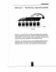
Getting Started REAR VIEW a — Soe TICS clone Figure : Rear View RS232 Adapter (VI100 Terminal Por) Reserved Cooling Fans . AC Voltage Select Switch (115v/230V) . Power Supply Unit Switch {On / Off) . Power Supply Unit 1 (Upper) . Power Supply Unit 2 (Lower) . Host channel adapter Port . Fan Door Screws 10. Power Supply Unit 1 LED indicator (Green) 11. Power Supply fail Indicator (Red) 12. Power Supply Alarm reset switch 13.
Getting Started Installing the Hard Disk Drives Step 1: Unlock the HDD tray by tuning the Key-lock to the correct position, Step 2 : Gently Pull out the HDD fray.
Getting Started Step 6 : Gently slide in the HOD tray. Step 7 : Lock the HDD tray. When powered on the Green LED will light up.
Getting Started Power-On and Self-Test When you connect the Disk Array to the Host computer, You should press the Push-button ON/OFF Power Supply Switch on the front panel. it will tum the Disk Ara on and the Self-Test will be started automatically. : Before you push down the power switch, you should turn the "1 symbol on the power switch cop and align it to point to the * + * mol on the front panel.
Getting Started Function Keys The four function keys at the top of the front panel perform the following functions : (1) Up Arrow / Right Arrow Use to scroll the cursor Upward / Rightward (4) Down Row / Left Arrow Use to scroll the cursor Downward / Leftward ( Enter) Use to confirm a selected tem (ESC) Use to ext a selection
Chapter 3 : " Configuration * | After completing the hardware installation, the disk array must be configured and the logical unit must be initialized before it is ready fo use. This can be accomplished through the following user interfaces : : + Front Panel function keys ( LCD Display } or + VIII terminal connected through the serial port | Monitor Port ) Yr The LCD display panel and a VI100 terminal can not be used at the same time.
Configuration Configuration procedures (via Front Panel) Main screen y Re-Con fig RAID No Yes RAID Level (5,3,1.
Configuration 5, Set RAID Level Move cursor the desired RAID Level (5, 3,1, 0, 0+1, None ), press * Infer * to confirm. Warning All data on the disk drives will be lost by changing the RAID Level. * RAID Level " None * = No Configuration 6. Set Hot Spare Disk Select" Yes " to set ane Disk Drive as a Hot-spare Disk. (valid for RAID Level § and 3 , the total number of Disk Drives installed must be more than 3 Disk Drives ) 7.
Configuration Configuration from VT100 Terminal Mode ] By connecting a VT1 00 compatible terminal or a PC operating ina terminal emulation mode, a configuration can be performed through this interface. To ensure proper communications between the “Disk Array” and the Internal, Please configure the VT 00 terminal settings to the values shown below : VT100 Terminal (or compatible ) Sef up Connection serial Port (COM 1 of COM 2) Protocol RS232 (Asynchronous) Cabling Noel-Modem cable Baud Rate 19.
Configuration Set RAID Level Move the cursor fo the desired RAID Level (5,3. 1,0,0+ 1, none), and Press * Enter * to confirm i. All Data wil be lost by changing the RAID level. Anton Hyper normal OUTPUT No Configuration | MEN mmm satire EX Disk Array Controllers {Version 2.2D 8/17/1998 Rh | { Recording RAID | Serial No: 040003 686005809 [DIKTAT Level i | Testing Serial Connection. . .
Configuration Each device on a SCS bus must be configured for a Target address (which Is a "SCSHD'). which Is different from any other device on the SCSI Bus. The default ID for this Disk Array I ID#0 If you need assign a different 1D# for your Disk Array, The available SCSI ID# for Arena You must assign a different 5CS! ID to each SCSI device on the SCS) Bus. The SCSI ID# must be unique for each device. [eT | aul —— Arena EX Monitor Utility v2.
Configuration Set Password Press * Enter * fo activate the password setting when you key-in the desired" Number * or " Character”. Press * ESC * for no change to the password. i EX Disk Array Controller aversion 2.2D 5/17/1998 {1 Contingent RAID] | Serial No: 000DCS5BE0DSENS iR11ramD Lever |} {Testing Serial 1 1 Bot Spare Dusk | Installed Memory = terabytes {18=c 8CS1 3D 1 {Host Chan i: TEST OK | [Termination | | Testing disk connection § § OK. Tsetse Password | | Testing disk connection 2 1 OR.
Chapter" Advanced Information * This chapter describes more Information about your Disk Array. The following items are describes in detail.
Advanced Information Disk Array Controller Block Diagram Micro Main Flash processor memory PROM RAMON LCD R$232 PCI 1 Bridge Monitor Port [REE] DE Controller Wide Controller Controller cassia controller I Disk | | Disk}] Disk | | Disk j Disk Disk Host 1 243] 4ll 8 6 channel!
Advanced Information Step 7. Select emulate VI100 mode After you have finished the VI100 Terminal setup, you may restart your Disk Array and press" Til + D "keys { In your Terminal Jo ink the Disk Array and Terminal together. Press display the disk any Monitor Utility screen on your Vitim Terminal.
Advanced Information 2. Press" Y" to confirm the Update. ] (ll touchdowns the DOST computer System.
Advanced Information 6. ype" Go" fo reconfirm and the firmware will begin fo be reprogrammed. 7, After verifying, please restart the Disk Array to activate the new firmware. encore downloading the new Firmware, shutdowns the host Scupper system. ice you Teddy CO downside the new peacetime (Y/N) ¥ ex you sure? (UM T Begin firmware £: ile transfer TOW. fo short download restart the RAID emcee Enter “Ga’ Reducer (do ta reconfirm.
Chapter 5 : " Hot Swap” This chapter explains how to remove and install the *Hot-Swap* parts without inf erupting the data access while the disk array is ON. The "Hot-Swap' parts Include : « Hard Disk Drives . Redundant Power Supply Units « Cooling Fans Follow the steps below and refer to the diagrams to remove and install the *Hot-Swap” parts.
Hot Swap d. Replace with a new Hard Disk Drive #t must be same capacity or greater than the faulty drive, if you replace with a Hard Disk Drive of Insufficient capacity, the Disk Ana's built-in buzzer will sound and the intelligent Auto-Rebuild function will not be started. ©For best performance, we recommend you swap with an identical Hard Disk Drive, e.
Hot Swap b.
Hot Swap Removing / Installing Cooling Fans . Unscrew the Fan door and open the door to a 90 degree position | Caution : Be careful. the high speed rotating fans may hom you. Don touch the rotating Fans, if necessary, Unplug the Fan power connector first.
Appendix Technical Specifications Microprocessor Cache Memory DRAM Slots Module Type DRAM Type DRAM Speed RAS access dime CAS access time Parity Read Cache Write Cache Firmware SCSI I/O Processor Serial Port Baud Rate Data Bits Stop Bit Parity RAID Levels Data Transfer Rate SCSI ID Assignment Tagged-command queuing Intel 1960 RD Minimum 4MB { 16MB*} Maximum 256MB (Two 128MB Sim Ms) wo 72 Pin Sim Ms EDO (Extended Data Output) 460ns Either parity or non-party Read-Ahead Write Back* Flash PROMOTE ,256K x 8 SYM
Interface : Host Bus Disk Bus Drives Maximum Fault Tolerant Capacity Drive MT BF Host Requirement Operating Systems Data Rebuild LCD Display Panel Cooling Fans Power Supply Capacity AC Input Voltage Environmental Relative Humidity Temperature Operating : Storage : Safety testing Dimensions Weight " * " Default Set lings Appendix Fast / Wide / Ultra-Wide SCSI-3 WIDE Fast AT-2 (PIO Mode , DMA Mode) Hot Swap, User Replaceable Up to Six cinch drives ( 1" height } >80GB >500,000 hrs Host Independent O/$ Independ
Hot Swap + Unplug the Fan connector * Unscrew the faulty cooling fan and replace with a good one Unimportant I The cooling fan's air flow must point to the fan door, please refer to the label on the cooling fan, * Plug in the fan connector, close the fan door and screw it in I Caution : The cooling fan will rotate immediately when you plug in the fan power connector.
Hot Swap ¢. Press the Power Supply Reset switch When you replace a new power supply unit, you should then push the power supply reset switch on the front panel or on the power supply frame to stop the buzzer alarm and fink the two power supply units together. ©The new power supply unit will link with the other unit Immediately and will start working after you press the power supply reset switch, and the buzzer waning noise will stop.
Hot Swap Removing / Installing the Redundant P/S Unit 1 There are two LED indicators on the front panel which display the status of the redundant power supplies. While the power supply is working property the two LED indicators light up * Green *, if any one of them fall, the LED indicator will go off and the redundant power supply buzzer alarm will sound.
Hot Swap Removing / Installing Hard Disk Drives ] a.
Advanced Information 5. Press *Y" fo confirm to download the new firmware and type confirm the new firmware update. Before downloading che new firmware, assurance the host CompuServe system. ire you ready to download the mew firearm? (Y/N) ¥ are you sure? (WM) ¥ Begin firearm rile transparent now. To abort download restart the RAID systems. nanosecond File transfer complete. Checksum = OXCART : OK. Hew firmware cress fer complete. Eater 'Go’ to update the firmware. Go Enter 'Go' to reconfirm.
Advanced Information 3. Select transfer * Send Text File * and press Enter.
Advanced Information Start fo Update Firmware 1. Move the cursor to " Update ROM " and press "Enter", va Hyphenation OUTPUT Arena €% Disk harry Controller | Version 2.2D 9/17/1958 | RA: [Serial Ns: 685009808 | SHIRAZ Level {Testing Serial Comnectlon...O0X |{tiac Spare Disk nacelle Eeyore = megabytes 118ec SCSI ID | {Host Chan 1: TEST OK § {Termination § | Testing disk connection Testing disk connection 2 1 OR. Testing disk connection 4 3 GR.
Advanced Information Updating Firmware 1.
Advanced Information 2. Install the memory a. The SIM memory modules will only fit in one orientation. b. Press the memory module firmly Info socket from a 45 degree angle, make sure that all the contacts are aligned with the socket, ¢. Push the memory module forward to a vertical position.
Advanced Information Memory Expansion Your Disk Array comes with 16MB of memory that is expandable to a fountain of 256MB by installing additional memory modules. The optional memory expansion socket is provided for installing memory module. These expansion memory module can be purchased from your dealer. « Memory Type : 60NS Extended Data Output ( EDO Simmers .
Configuration Save & Restart Select the Save & Restart function and press * Enter * fo save and activate your selections. Warning! All data will be lost If you change the RAID level saving configuration changes causes the disk array controllers working parameters to change. This can produce unpredictable results if it occurs during Host and Array activity. Alt activity fo the controller should be stopped before saving configuration changes. keens EX Disk Array Controller {Version 2.
Configuration Terminating a SCSI chain Is achieved by adding a terminator to each end of the SCSI Bus. The Disk Stay supports active termination in the controller's SCSI end. Termination "enabled" must be set when the Disk Array Is at one end of the SCSI Bus. STAR Contrariety RAID] [RAID Level | 1] fot Spare Disk] [i Set SCSI 1B | [termination | |i ENABLE | DISABLE HED rennin EX Disk Array Controller Version 2.
Configuration select " Yes * to set One Disk Drive as a Hot Spare Disk. This Function is valid in RAID level 5 and RAID level 3 the total Disk Drives installed must be more than 3 Disk Drives. ( Disk Drives number > 3) Ares EX Capacitor cyclic vivid No Configuration | ~ OUTPUT | hens EX Disk Array Controller vermilion 2.2D 3/17/1598 | {Re-Contiguity RAID] J RAID Level | 11Het Space Disk) Spare Disk-+ sartorial No: | Testing Serial Connection...
Select " No" for setting : * SCSI ID", * Terminator *, * Password * Configuration Select * Yes " for setting all the configurations Anz per seminal ~ hens EX Mentor Puerility v2.2 No Configuration | OUTPUT w ANY | arena EX Disk Array Controller Ken u--—+ }contingent RAID] | 1 RAINBOW [Version 2.20 9/17/1998 [Serial No: 0BOONISBE009908 | Testing Spiel Connection. ..
Configuration Configuration procedures { VI100 Terminal ) Main screen Re-Con fig RAID Yes RAID Level None ) Hot Spare Disk (Yes/No) No Set SCSI ID (0~18) Termination (Enable / Disable) Set Password (4 Digital Save Configuration No eo Yes & Restart v No Update Firmware Yes i
Configuration 8. Termination Terminating a SCSI chain is achieved by adding a femininity to each end of the SCSI bus. The Disk Array supports active termination af the controllers SCSI end. Termination "enabled" must be set when the Disk Array is af one end of the SCSI Bus. 9. Set Password Press " Enter ' fo activate the Password setting. When the cursor stop on the desired "number' or "character, Using" § " and * 1 * function keys to choose the desired characters and then press * Enter * to confirm it.
Configuration Starting the configuration 1. Power-on the Disk Array. At the end of the power-on self test program, the LCD displays the current system status. 2. Press the front pane * Enter * key fo access the built-in configuration program. 3. When the screen displays the password prompt and asks you to " Enter Password * Enter Password omen press " Enter " 4 times to Input the default password { default password is * 4.
Configuration Configuration from the front Panel | The LCD Display front panel function keys are the primary user interface for the Disk Array. Except for the "Firmware update" all configuration can be performed through this interface.
Getting Started LCD Status Panel Located the LCD panel, the LCD status panel Informs you of the Disk Array's current operating status at a glance. Upon activating a certain function, a symbol or icon corresponding to that function will appear in the display window. The symbol will remain in the display window indicating the status of the Disk Array. Identifying the status on the LCD The following illustration shows the symbols (characters) been used and their representation.
Getting Started LED Display & Function Keys LODE Display Shown below is the LED Display. Please refer fo the illustration, the LED inform you of the Disk Array's current operating status. Upon activating a certain function, the corresponding LED Indicator should fun on indicating that the feature is engaged. Figure : LED Display LED Descriptions 1. Power Unit 1 Indicator fight up : “Green, it Highs when fhe Power Unit 1 Is plugged and operating functionally, 2.
Getting Started Host Linkage With the H Dds} Installed correctly, you are ready to connect the Disk Array fo your Host computer. Use a shielded twisted-pair SCSI cable to connect your Host computer to the Disk Arrays built-in 68 pin SCSI adapter port, Connect the Host computer as shown below : Disk Array Host Computer Figure : Host linkage For safety reasons, make sure the Disk Array and Host Computer are muted off when you plug-in the SCSI cable.
Getting Started Step 3: Insert HDD into the tray Step 4. Screw In the hard drive.
Getting Started Power Source Choosing a Working Voltage The Arena can run ether on AC 110V or AC 220V Slide the AC voltage select switch on both of the two power supply units to the correct position which corresponds with the wall outlet supply voltage. FE i ERIS Wrong AC Voltage Input will harm the power supply and cause serious damage fo the Disk Array. ® Figure : Power Source This Disk Array is supplied with an AC power cord equipped with a 3-wire grounding type plug.
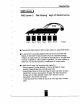
Getting Started Identifying Parts of the Disk Array i Front View ] Figure : Front View 1. HDD Trays Power Supply Switch (On / Off } , Function Keys (1, | , Enter, ESC) . Power-On Indicator ( PWR Unit 1, PWR Unit 2) . Power Supply * Alarm * Reset . Host Computer Access Indicator . HDD Tray Lock ( Lock / Unlock ) .
Getting Started Unpacking & Checklist Before unpacking your Disk Array , prepare a clean and stable place to put the contents of your Disk Array's shipping container on. Altogether, you should find the following terns in the package : © The Disk Array * One AC power cord * One External SCSI cable . Keys ¢ User Manual Remove all the rems from the carton. If anything Is missing or broken , please inform your dealer immediately. Save the cartons and packing materials that came with the Disk Array.
Multi-SCSI Format support The Disk Array provides one Ultra Wide SCSI channel for connecting to your host system. With proper cabling, tf may support Narrow or Wide; Standard, Fast or Ultra SCSI formats.
Introduction Summary Comparison of RAID Levels ] RAID Common Description Rays | Dora Data Level Name Capacity] Reliability | Transfer [Cap achy Data distributed across the 0 Disk disks In the array. (N) Low Very Striping Ne redundant information disks High provided.
Introduction RAID Level 5: " Independent Access Array with Rotating Parity » High Data Reliability & Transfer Capacity Disk Disk Disk Disk Disk S Disk Physical P : Parity When RAID Level 5 technology is combined with cache memory to Improve Its write performance, the result can be used In any applications where general purpose disks would be settable. for read only or read mostly application YO loads, RAID Level 5 performance should approximate that of a RAID Level 0 array.
Introduction RAID Level 3 : " Parallel Transfer Disks with Parity * High Data Reliability & Highest Transfer Capacity Disk Disk Disk Disk Disk Disk Physical Pp: Party RAID Level 3 technology use a dedicated parity disk to store redundant information about the data on several data disks. RAID Level 3 is an excellent choice for applications which require single stream YO with a high data transfer rate.
Introduction @ RAID level 0 arrays are not particularly suitable for + Applications which make sequential requests for small paramount of data. These applications will spend most of their I/O time waiting for disks to spin, whether or not they use striped nays as storage media. Applications which make synchronous random requests for small amounts of data.
Introduction General RAID Concepts Comet installation of the disk array requires on understanding of RAID technology and the concepts described in this section. Definition RAID is an acronym of Redundant Array of Independent Disks . A RAID Is a Disk Array in which part of the storage capacity is used to record redundant information about the user data stored on the remainder of the storage capacity.
introduction This section provides an overview of the features, For more detailed Information, please refer to the technical specifications appendix at the end of this manual . Arena includes the following features Easy Operation As everyone knows, conventional Disk Arrays are designed for experienced computer specialists.
Configuration Procedures Starting the Configuration Configuration from VT100 Terminal Mode Configuration Procedures Main Screen Re-con fig RAID Set RAID Level Hot Spare Disk Set SCSI ID# Termination Password Save & Restart Chapter 4 : Advanced Information Memory Expansion RAID Controller Brock Diagram Updating Firmware Setting Up VT100 Terminal Emulation in Windows 95° Start to Update Firmware Chapter 5 : Hot Swap Removing / Installing Hard Disk Drive Reproving / Installing Redundant Power Supply Unit Remov
About This Manual This manual serves as a useful guide you can refer to when you wish to install and operate your Disk Array. It includes the following information : ® Chapter 1 : “ Introduction * Introduces you to your new Disk Arrays features and general RAID concepts. ® Chapter 2 : * Getting Started * Describes general information about this Disk Array. ® Copter 3 : " Configuration Provides a Quick and Easy way to setup this Disk Array.
X Na CATION 15. } § [Ez] . If an extension cord or a power center is used with this product, make sure that the total of all products plug info the wall outset does not exceed the ampere rating. . Do not place the Disk Array where the cord wil CAUTION 13. be walked on. Never push any kind of object into this product through cabinet gaps and openings, they may ouch dangerous voltage points cause a risk of fire or electric shock. . Unplug the power cord from the wall outlet before cleaning.
Copyright Notice © 1998 Macaroni Informational Co., Ltd. All rights reserved. No part of this written material may be reproduced, stored in a retrieval system, used in any form of by any means, electronic or mechanical, photocopying, recording, or otherwise, without the written permission of Macaroni International CO., LTD.