
Product Manual


ALMACENAMIENTO
1. Mientras no lo esté usando debe
almacenar el compresor y las
mangueras en un sitio seco y frío.
2. Debe drenar el tanque.
3. Debe desconectar las mangueras y
colgarlas con los extremos hacia
abajo para que se drenen.
EX8000, WL5000 Serie de modelos para contratistas
17 Sp
Mantenimiento
(Continuación)
LUBRICACION
Este compresor no requiere lubricación.
PROTECTOR TERMICO
Esta com-
presora
está equipada con un protector de
sobrecarga térmica de reposición
automática.
!
PRECAUCION
Si el protector térmico apaga al
compresor con mucha frecuencia puede
ser por lo siguiente:
1. Voltaje bajo.
2. El cordón de extensión es muy corto
o del calibre inadecuado.
3. El filtro de aire está atascado.
4. La ventilación es inadecuada.
Para
poder
arrancaar de nuevo el motor, se debe
dujar enfriar. Ele motor se pondra en
marcha de nuevo, sinninguna senal de
aviso, si se daja conectado a un
tamacorriente y si el motor ya esta
enceneito.
!
PRECAUCION
4
Portable Air Compressors
Operation (Cont.)
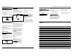
REGULATOR KNOB
1. This knob controls air pressure to an air
operated tool, or paint spray gun.
2. Turning knob clockwise increases air
pressure at outlet.
3. Turning counterclockwise will lower air
pressure at outlet.
4. Fully counterclockwise will shut off flow
of air completely.
REGULATED OUTLET GAUGE
1. This gauge shows at-a-glance, air
pressure at outlet. Air pressure is
measured in pounds per square inch
(PSI).
2. Be sure this gauge reads ZERO before
changing air tools or disconnecting hose
from outlet.
TANK PRESSURE GAUGE
Gauge shows pressure in air receiver
indicating compressor is building pressure
properly.
Maintenance
Release all
pressure and
disconnect power before making any
repair.
1. Check compressor for any visible
problems, especially check air filter to be
sure it is clean.
2. Pull ring on safety valve and allow it to
snap back to normal position.
!
WARNING
Safety valve must
be replaced if it
cannot be actuated or it leaks air after ring
is released.
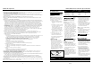
3. Daily with compressor shut off:
Depressurize system prior to draining
tank. Drain moisture from tanks by
opening drain cocks underneath end of
tanks.
4. Turn power OFF and clean dust and dirt
from motor, tank, air lines and pump
cooling fins.
NOTE: The air filter in the filter housing on
the side of the head must be checked and
cleaned periodically, more often if used
under very dusty conditions or when a
great deal of fog from spraying is allowed
to circulate near unit.
IMPORTANT: Unit should be located as
far from spraying area as hose will allow
to prevent over-spray from clogging filter.
FILTER REMOVAL, INSPECTION AND
REPLACEMENT
To change a filter, pull off the filter
housing cover. If filter element is dirty,
rotate filter cover so the holes line up with
clean element material and snap cover
onto housing. If filter element has no
clean areas, replace element or entire
filter.
LUBRICATION
This is an oilless type compressor requiring
no lubrication.
THERMAL OVERLOAD PROTECTOR
This compressor is
equipped with an
automatic reset thermal overload
protector which will shut off motor if it
becomes overheated.
!
CAUTION
!
WARNING
If thermal overload protector shuts motor
OFF frequently look for the following
causes.
1. Low voltage.
2. Wrong gauge wire or length of
extension cord.
3. Clogged air filter.
4. Lack of proper ventilation.
The motor must be
allowed to cool
down before start-up is possible. The
motor will automatically restart without
warning if left plugged into electrical
outlet, if the motor is turned on.
STORAGE
1. When not in use, hose and compressor
should be stored in a cool dry place.
2. Tank should be drained of moisture.
3. Hose should be disconnected and hung
open ends down to allow any moisture
to drain.
!
CAUTION
Figure 5
Figure 4
Close
Open
Attach
Hose
Drain
Cock
Figure 6
www.chpower.com
Notas