MXL017/65 & 85 Target (Twin & Single) Installation & operating instructions UK contact: Helpline: Email: Web: +44 (0)1553 811000 support@maxview.co.uk www.maxview.co.
Contents: Introduction 2 Proper use & operation 2 Safety precautions 3 Application example 4 Connections & features 5 Product contents 5 Required tools and equipment 5 Selecting an installation location 6 Positioning Control Box 6 Attaching Antenna Mount Plate 7 and LNB Park Plate Electrical installation 8 Attaching Antenna Unit to 9 Mount Plate Installing cables 9 Installing Cable Entry Plate 10 Installing Control Box 10 Connection diagram 11 Attaching Satellite Dish to Uni
Safety precautions: Read this manual carefully and become familiar with your satellite antenna. Understand its applications, its limitations and any hazards involved. Failure to follow all instructions listed below may result in electric shock, fire and/or serious injury. Maxview declines all responsibility in the event of incident or accident if they are due to a non observation of the installation instructions or the way the product is used.
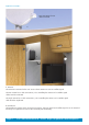
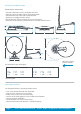
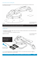
Application example: Note: LNB image shows different model A B A. Antenna The Antenna is mounted to the roof. It uses electric motors to scan for satellite signals. The twin variant has 3 cable connections; 1 for controlling the motors and 2 satellite signal cables from the twin LNB. The single variant has 2 cable connections; 1 for controlling the motors and 1 satellite signal cable from the single LNB. B.
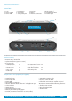
Connections and features: Control Box: 1. Fuse 2. Power Switch 3. Power LED 10. Not required 11. Installation Button 12. Power Input 7. Receiver 8. LNB in 9. Antenna Connectors 4. Sync Button 5. Status LNB 6. USB update port 3 5 6 Refence page 13 for interface information 1 2 4 11 7 8 9 10 Product contents: > Antenna Unit / Control Box > 65/85cm Antenna (separate carton) > Accessory Pack > LNB Park Plate x1 > Control Box bracket x 2 > No.10 Screws x6 > No.
Selecting an installation location: Positioning the Antenna Unit > Check for obstructions such as roof lights and vents. > Check for electrical cables beneath screw fixing points. > Check Antenna Unit cables will reach Control Box (Maxview can supply extended cables).
Attaching Antenna Mount Plate & LNB Park Plate: 1. Remove Antenna Unit from wooden transit packaging 2. Remove mounting plate from Antenna Unit by removing 6 x M6 nuts using 10mm spanner 3. Clean roof, Mounting Plate and LNB Park Plate in accordance with adhesive manufacturer’s guidelines 4. Mark a centre line for the antenna making sure dish will not overhang vehicle 5. Align notches on plate with centre line 6. Mark the position of 6 screw fixing holes 7. Mark position of LNB Park Plate 8. Drill 6 x 2.
Electrical installation: Whilst the adhesive is curing prepare the electrical connections for the Control Box. The Control Box requires a permanent 12V supply and a secondary 12V supply that provides power when the engine of the vehicle is running. Note: the brake light circuit is not suitable. It is recommended to create a new circuit direct to the battery using a minimum cable cross sectional area of 2.5mm2 and an inline fuse of 5A.
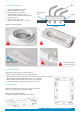
Attach antenna unit to mounting plate: Carefully lower the Antenna Unit onto the Mounting Plate and re-attach the M6 Nuts and Washers that were previously removed. Caution: Note: LNB image shows different model. Replace Nylon locking nuts if they have been removed more than twice. The locking action of the Nylon becomes less effective if repeatedly assembled and disassembled. Installing cables: 1.
Installing Cable Entry Cover 1. 2. 3. 4. Plan your installation carefully Drill a 32mmø hole in roof Prepare surface for adhesion Apply sealant as shown in A,B,C (we recommend Sikaflex-512 Caravan)* 5. Position top hat 6. Position cable entry cover 7.
Connection diagram: TV A Satellite Receiver/s D B C 5A Fuse Not required Key: A: Satellite Cable B: Satellite Cable C: Antenna Cable + Ignition D: Cable for PVR or additional Satellite Receiver Attach Satellite Dish to Antenna Unit 1. Ensure Antenna Unit is free from obstacles. 2. Press installation button on reverse of Control Box to elevate antenna. Once elevated turn off power to Control Box and remove fuse. 3.
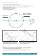
Finding a satellite: Before starting check there is a clear line of sight to the southern sky. All television broadcasting satellites have a geostationary orbit which means their location is fixed above the earth’s equator. Satellites also have a limited range of transmission so use the Zone maps included in the appendix to check your location is suitable for reception.
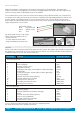
Interface details A B C D A. Select satellite B. LED shows you which satellite is selected C. SEARCH - Press and release PARK - Press and hold for 3 seconds D. Satellite found LED (green FOUND) How to operate your system 1. Turn on Power on Flashes green Switch the power on. The LED flashes green on the last satellite you selected. 2. To change satellite* Press Flashes green *If required. Press SAT to scroll through satellite selection. Eg. New selected SAT LED will flash green.
4. Satellite Found Solid green Solid green Once the satellite has been found the OK LED and the satellite selected will show solid green. 5. Park System Flashes green Park PARK - Press and hold for 3 seconds. LED’s 1 to 5 flash green to indicate system is collapsing. Once fully collapsed, control panel can be powered off. Ignition mode: The ignition mode is a safety feature that automatically lowers the antenna and prevents accidental operation whilst travelling.
Software update: To keep your Seeker up to date with the latest satellites Maxview has incorporated a USB port on the front of the Control Box. The Seeker has the ability to update its satellite data and its operational software from a simple USB flash memory stick. Please visit www.maxview.co.uk - search: Target - Downloads for latest software and a guide to installation. Preparing a USB Flash Memory Stick: 1. Use a blank USB flash memory stick formatted to FAT or FAT32 2. Format USB stick: 3.
Antenna Control Box Fault finding: Problem Actions No power Check Fuse Check Power cable connection Leisure battery voltage is low Fuse blows repeatedly Check Fuse rating is 3A Check antenna unit is not obstructed Contact Maxview Customer Service USB update failed Check file was added to a blank FAT formatted USB memory stick After update check text file added to USB memory stick Contact Maxview Customer Service Antenna stuck in elevated position DO NOT TRAVEL UNITIL ANTENNA UNIT
All flashes green Solid green C. Ignition mode parking. When the antenna is parking using the Ignition (green wire) all sat LEDs flash green All solid red D. Ignition mode parked. When system parked during ignition mode all the SAT LED’s stop flashing green and ALL 5 LED’s go solid RED. During Ignition mode ALL control buttons have no function (locked). Once ‘Ignition off’ last satellite found LED start to flash and ready to search (keys active again). Solid orange Flashes red E. Azimuth Error.
Skew adjustment: Astra 2 - 28.2° Skew adjustment is required when signal strength is weak at the limit of a given satellites’ reception area. It involves adjusting the angle of the LNB on the roof mounted antenna unit. Caution: Follow general safety advice on page 3 when adjusting antenna unit. + - Note: LNB image shows different model. Astra 1 - 19.2° Page 18 Visit: www.maxview.co.
3 year guarantee: Every new Target System is thoroughly inspected and tested before leaving the factory and is covered by our three years guarantee from the date of original purchase. Maxview is responsible for the cost of a replacement part if the original part is determined to be defective under the terms of guarantee. The customer is responsible for the cost of replacement parts after three years. This guarantee does not cover installation or external wiring.
Specifications: Operating: Average search time 30-60 seconds typical Future proof with free software updates via a USB stick - see page 15 Low stream line profile, only 17cm in park position 5 Pre-programmed including: Astra 1 19.2°, Astra 2 28.2°, Astra 3 23.5°, Hotbird 13° & Thor 0.8° Power: Powering: Power Consumption: Standby Current: Fuse Type: 12V operation Maximum 2A consumption during search 0.