DYN-6209-01 / DYN-6209-02 / DYN-6209-03 2 Person FAR Infrared Sauna Owner’s Manual CARBON MODEL SAUNA SAUNA IS FOR INDOOR USE ONLY 120VAC 15AMP Dedicated Circuit Required Carefully and thoroughly read this Owner’s Manual before using/operating the sauna. We recommend keeping this Owner’s Manual for regular review and future reference.
TABLE OF CONTENTS Packing List 2 Visual Assembly Diagrams 6 Parts Description 9 Assembly Instructions 15 Operating the Sauna 21 Tips for Using Your Sauna 24 Safety Instructions 25 Safeguards for Your Sauna 27 Troubleshooting Guide 27 Warranty 33 Warranty Card 35 WARNING: Visually inspect all heaters before assembly to make sure they are not damaged. Any excessive vibrations during transport could cause damage to the heating elements.
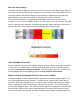
What Are Infrared Rays? Infrared is the band of light we perceive as heat. We cannot see this band of light with the naked eye, but we can feel this type of light in the form of heat. Our sun produces most of its energy output in the infrared segment of the spectrum. Infrared rays heat your body without having to heat the air in-between. This process is called conversion. The infrared is divided into 3 segments by wavelengths measured in microns: Near Infrared – 0.76-1.5 microns; Middle Infrared – 1.5-5.
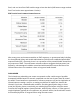
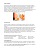
5mG, and our Near Zero EMF models range at less than 3mG (NIR heaters range at about 5mG-7mG at the same approximate 2 inches). EMF Levels from Common Homes Sources After many years and numerous studies on EMF exposure, no government body including the Occupational Safety and Health Administration (OSHA) have established permissible exposure limits (PEL). Currently, there is no consensus on the potential health hazard from any exposure to EMF.
HOW IT WORKS Infrared Saunas differ from traditional saunas in that they use infrared radiant energy to directly penetrate into the body's tissue to produce perspiration. Traditional saunas use steam to heat the air inside the sauna, which then heats your body until you begin to perspire. In order for this to be effective, temperatures would need to reach in the upwards of 190 degrees Fahrenheit. Infrared saunas only need a temperature of up to 120 degrees Fahrenheit to obtain the same effect.
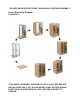
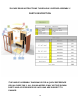
*PLEASE READ INSTRUCTIONS THOROUGHLY BEFORE ASSEMBLY* Visual Assembly Diagram DYN-6209-01 *THE ABOVE ASSEMBLY DIAGRAM IS FOR A QUICK REFERENCE VISUAL GUIDE ONLY. ALL SAUNA MODELS MAY NOT BE SHOWN. PARTS AND ACCESSORIES DO VARY AND ARE SUBJECT TO CHANGE.
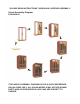
*PLEASE READ INSTRUCTIONS THOROUGHLY BEFORE ASSEMBLY* Visual Assembly Diagram DYN-6209-02 *THE ABOVE ASSEMBLY DIAGRAM IS FOR A QUICK REFERENCE VISUAL GUIDE ONLY. ALL SAUNA MODELS MAY NOT BE SHOWN. PARTS AND ACCESSORIES DO VARY AND ARE SUBJECT TO CHANGE.
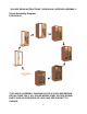
*PLEASE READ INSTRUCTIONS THOROUGHLY BEFORE ASSEMBLY* Visual Assembly Diagram DYN-6209-03 *THE ABOVE ASSEMBLY DIAGRAM IS FOR A QUICK REFERENCE VISUAL GUIDE ONLY. ALL SAUNA MODELS MAY NOT BE SHOWN. PARTS AND ACCESSORIES DO VARY AND ARE SUBJECT TO CHANGE.
*PLEASE READ INSTRUCTIONS THOROUGHLY BEFORE ASSEMBLY* PARTS DESCRIPTION *THE ABOVE ASSEMBLY DIAGRAM IS FOR A QUICK REFERENCE VISUAL GUIDE ONLY. ALL SAUNA MODELS MAY NOT BE SHOWN. PARTS AND ACCESSORIES DO VARY AND ARE SUBJECT TO CHANGE.
*PLEASE READ INSTRUCTIONS THOROUGHLY BEFORE ASSEMBLY* PARTS DESCRIPTION *THE ABOVE ASSEMBLY DIAGRAM IS FOR A QUICK REFERENCE VISUAL GUIDE ONLY. ALL SAUNA MODELS MAY NOT BE SHOWN. PARTS AND ACCESSORIES DO VARY AND ARE SUBJECT TO CHANGE.
*PLEASE READ INSTRUCTIONS THOROUGHLY BEFORE ASSEMBLY* PARTS DESCRIPTION *THE ABOVE ASSEMBLY DIAGRAM IS FOR A QUICK REFERENCE VISUAL GUIDE ONLY. ALL SAUNA MODELS MAY NOT BE SHOWN. PARTS AND ACCESSORIES DO VARY AND ARE SUBJECT TO CHANGE.
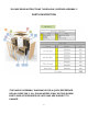
I. Power Supply The POWER SUPPLY is the control center of the sauna room. It is installed on the rooftop and has inputs/outputs connected to it. (see Figure 1) Figure 1 POWER IN - main power of the sauna room HT1, HT2, HT3, HT4, HT5, HT6 – heat emitter cords LAMPROOF – roof lamp power (optional) LIGHTING – chromotherapy lights PANEL CONTROL – control panel FUSE RESET – protects against power II.
III. MP3 Auxiliary Port The MP3 Auxiliary Port allows you to connect a MP3 player or other device with the auxiliary function to the speakers in the sauna room for your listening pleasure. (see Figure 2) Figure 2 IV. Buckles A. External Buckles The external buckles are used to connect the LEFT and RIGHT SIDE PANELS to the REAR PANEL. (see Figure 3) Figure 3 B. Guide and Guide Inserts The guide and guide inserts are used to connect the FRONT PANEL to the RIGHT SIDE PANEL and the LEFT SIDE PANEL.
Figure 4 V. Panel Descriptions For easier assembly, please understand and distinguish the differences between each panel. A. Floor Panel When the FLOOR PANEL faces upward, the surface will be flat. (see Figure 7) B. Understanding the Difference Between the Top and Bottom of the Wall Panels The (4) panels are in the upright position when the moldings are at the top. The moldings will be facing inward towards the interior of the sauna room.
Figure 6 D. Understanding the Difference Between the Inside and Outside of the Rear Panel You will find the heat emitters on the inside of the REAR PANEL. Assembly Instructions 1. Choose a good location to assembly the sauna a. The location must be dry, level, and away from any source of water. b. The dedicated outlet must be easily accessible. c. Two adults will be needed to assemble. d.
Figure 7 3. Installing the FRONT PANEL with the RIGHT SIDE PANEL with GLASS DOOR A. Place the FRONT PANEL up against the FLOOR PANEL as seen in Figure 8. There will be a molding at the bottom of the FRONT PANEL that will rest on the FLOOR PANEL. One adult will need to hold the FRONT PANEL stationary up against the FLOOR PANEL. The second adult will need to lift the RIGHT SIDE PANEL up and onto the FRONT WALL PANEL.
Figure 11 5. Installing the REAR PANEL A. Place the REAR PANEL up against the FLOOR PANEL. There will be a molding at the bottom of the REAR PANEL that will rest on the FLOOR PANEL. You may need to open up the RIGHT SIDE PANEL and LEFT SIDE PANEL to fit the REAR PANEL between the two. Please note that the REAR PANEL will fit with the RIGHT SIDE PANEL and LEFT SIDE PANEL like a puzzle as it inserts into both side panels.
C. Install the BENCH by sliding it over the horizontal bench guides on the side panels. Push the BENCH all the way in until it touches the REAR PANEL and is secured in place. Make sure to install the BENCH with the smooth and finished side facing up. Option 2 A. Installing the BENCH HEAT EMITTER PANEL can be a little tricky. You will need to slide the BENCH HEAT EMITTER PANEL into place at an angle as indicated in Figure 13.
8. Installing the ROOF PANEL A. The side of the ROOF PANEL with the ceiling vent will be situated towards the rear of the sauna. Two adults can carefully lift the ROOF PANEL up and onto the top of the sauna room. Be careful when setting the ROOF PANEL into place as the cords and wire harness will need to be fed up to the topside of the ROOF PANEL. (see Figure 15) Figure 15 9. Connecting the plugs on the ROOF PANEL A. Connect the cords according to their respective labels. (see Figure 16) B.
Figure 17 Please Note: Some sauna models are shipped with a spare TEMPERATURE SENSOR (inside the Accessory Box) in the case that the TEMPERATURE SENSOR is damaged during transit. The manufacturer decides this according to sauna models and packaging. 11. Installing the ROOF DUST COVER (optional) A. Place the ROOF DUST COVER over the top of the ROOF PANEL. Be cautious when pulling the power cord through the hole in the ROOF DUST COVER. When the edges are aligned, screw the ROOF DUST COVER into place.
Operating the Sauna NOTE: Before the sauna is turned on, remove plastic protective covering from the CONTROL PANELS. Please check and confirm that the connections to the POWER SUPPLY (including the power cord), HEAT EMITTERS, CD/RADIO, and TEMPERATURE SENSOR are connected properly and are snug and tight. The power supply voltage and frequency must match the requested voltage and frequency of the sauna (120VAC 15AMP Dedicated Circuit or 120VAC 20AMP Dedicated Circuit).
1. Plug the sauna into the wall outlet. 2. Press the POWER button once. The POWER light will come on, the TIME DISPLAY will show 90 (minutes), the TEMPERATURE DISPLAY will show 1510F / 660C, and the control panel will flash. 3. Press the up/down arrows under the TIME DISPLAY to adjust the amount of time you want the sauna to remain on. Press the C/F button to choose between Celsius and Fahrenheit. Press the up/down arrows under the TEMPERATURE DISPLAY to adjust the temperature setting.
panel. The white light will come on. While pointing the remote at the ceiling light, you can press any of the colors on the remote and that color will be displayed. You can use the SHADE button on the remote to go through a sequence of colors. If you want to turn the light off during your sauna session, you can press the POWER button on the remote. Please note: You must be inside the sauna room for the remote to work. 9. Bluetooth can be used on the sauna room.
Please keep in mind that you can either preheat the sauna to the set temperature before entering or sit inside the sauna as the temperature rises. In addition, you will increase the time it takes for the sauna to reach the set temperature if you enter the sauna room before it has reached the set temperature. Also, the most commonly used temperature setting is between 118 degrees Fahrenheit / 48 degrees Celsius and 122 degrees Fahrenheit / 50 degrees Celsius.
6. At the first sign of a cold or flu, increasing your sauna sessions may be beneficial in boosting your immune system and decreasing the reproductive rate of the virus. 7. To help relieve sore and tense muscles, massage the affected areas during your sauna session. 8. To treat your ankles and feet more effectively, you can elevate them and move them close to one of the heat emitters to achieve a deep heating effect. 9.
high blood pressure, circulatory system problems, diabetes, or other medical conditions should consult with a medical physician prior to using the sauna. 9. Persons using medications should consult with a medical physician before using the sauna. Some medications may induce drowsiness while other may affect the heart rate, blood pressure, and/or blood circulation. 10. Use care when exercising before and after sauna use. 11. Never sleep inside the sauna 12.
operation. If for any reason your sauna does not seem to be operating properly, discontinue use and contact Customer Service. Safeguards For Your Sauna 1. Do not install the sauna near water, near a bathtub (if water will splash on the sauna), near a shower (if water will splash on the sauna), in a wet basement, or near a swimming pool (if water will splash on the sauna). 2. Do not use liquid cleaners or aerosol cleaners on the sauna. Unplug the sauna from the wall outlet before cleaning.
applicable). Go to the roof, and also check that the heat emitter cords are properly connected snug and tight to the cords on the roof and that those cords are properly plugged into the power supply (snug and tight). Solution: If some of the heat emitters are working, then the ones which are not working may have been damaged or are not properly connected. Check that the heat emitter cords are properly connected snug and tight. If the issue continues, then the particular heat emitter may be damaged.
control panel may have been damaged and will need to be replaced. Before contacting Customer Service, remove the wood frame holding the control panel in place to gain access to the “CTRL” connection behind the control panel. Once you remove the control panel from the wall panel, you can disconnect and reconnect the connection making sure it is snug and tight. Contact Customer Service for any additional troubleshooting.
Step B: 1. Make sure to first unplug the sauna’s power cord from the wall outlet or power source. If the sauna is hard wired straight to the breaker in the Electric Panel, turn the breaker to the “OFF” position. 2. Remove the exterior wood frame around the exterior control panel. Simply unscrew the screws holding the wood frame on. 3. Once the wood frame has been removed, lift the control panel up and out. On the backside of the control panel, you will see a connection plug.
7. Speaker Noise Solution: If you are hearing a humming noise from either speaker or both speakers while the Bluetooth feature is connected with your musical device, then there may be an issue with the control panel(s). To confirm this, please connect your musical device using the MP3 AUX wire that came with the sauna room to connect your musical device to the sauna speaker system. You will connect one end of the MP3 AUX wire to your musical device and the other end to the MP3 Jack on the ceiling.
and time to 90 minutes. Record the starting/beginning temperature and the temperature after 15 minute intervals up to 90 minutes (do not enter the unit or open the door during this test). If the sauna room goes above 130 degrees F (usually after about 40 to 50 minutes of preheating with a beginning temperature above 70 degrees F) at any given time, then we know that the heat emitters are working successfully.
Limited Lifetime Warranty 5 Year Limited Warranty: Golden Designs, Inc. under the Dynamic brand name warranties the wood, structure, heating elements, and electronics against defects in material and workmanship for a period of 1 to 5 years from the original date of purchase. This sauna is for INDOOR use only. Placing your sauna outdoors will VOID this warranty. Any damage due to exposure to outdoor elements such as rain, snow, sun, wind or extreme temperatures will not be covered by this warranty.
Use of product not in accordance with instructions Worn out receptacle Surface cracks are not considered defects in material or workmanship, as they are normal characteristics of all woods. This includes minor cracks due to wood expansion and contraction. Note: Since the wood used in construction has been kiln dried, a certain amount of expansion and contraction occurs in the wood in a sauna environment. Disclaimers Golden Designs, Inc.
WARRANTY CARD Congratulations on your purchase of an Infrared Sauna from Golden Designs, Inc. Please take the time to complete the following Warranty Card and mail it back to: Golden Designs, Inc. 3550 Jurupa Street, Unit B Ontario, CA 91761 Please include a copy of your sales receipt showing date of purchase as this will serve as proof of purchase. Warranty will be VOID if the following warranty card is not mailed back within 60 days of purchase date along with proof of purchase.