W10135154B EnFrv10.qxd:YB70809-10135134A 4/20/10 2:42 PM Page 1 INSTALLATION INSTRUCTIONS COMMERCIAL DRYER – Gas or Electric INSTRUCTIONS POUR L’INSTALLATION D’UNE SÉCHEUSE COMMERCIALE – À gaz ou électrique Table of Contents/Table des matières . . . . . . . . . . . . . . . . . . . . . . . . . . . . . . . . . . . . . . . . 2 W10135154B www.maytagcommerciallaundry.
W10135154B EnFrv10.qxd:YB70809-10135134A 4/20/10 2:42 PM Page 2 TABLE OF CONTENTS TABLE DES MATIÈRES DRYER SAFETY............................................................................ 2 INSTALLATION REQUIREMENTS .............................................. 4 Tools and Parts .......................................................................... 4 Location Requirements.............................................................. 5 Electrical Requirements ....................................
W10135154B EnFrv10.qxd:YB70809-10135134A 4/20/10 2:42 PM Page 3 WARNING: For your safety, the information in this manual must be followed to minimize the risk of fire or explosion, or to prevent property damage, personal injury, or death. – Do not store or use gasoline or other flammable vapors and liquids in the vicinity of this or any other appliance. – WHAT TO DO IF YOU SMELL GAS: • Do not try to light any appliance. • Do not touch any electrical switch; do not use any phone in your building.
W10135154B EnFrv10.qxd:YB70809-10135134A 4/20/10 2:42 PM Page 4 IMPORTANT: The gas installation must conform with local codes, or in the absence of local codes, with the National Fuel Gas Code, ANSI Z223.1/NFPA 54 or the Canadian Natural Gas and Propane Installation Code, CSA B149.1. The dryer must be electrically grounded in accordance with local codes, or in the absence of local codes, with the National Electrical Code, ANSI/NFPA 70 or Canadian Electrical Code, CSA C22.1.
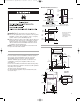
W10135154B EnFrv10.qxd:YB70809-10135134A 4/20/10 2:42 PM Page 5 Location Requirements Minimum Installation Clearances 14" (356 mm) max. 15" (381 mm)* Closet door 0" (0 mm) 0" (0 mm) 0" (0 mm) 1" (25 mm) Recessed front view Closet side view *Additional clearances for wall, door, and floor moldings may be required or if external exhaust elbow is used. 3" (76 mm) If installing a gas dryer: IMPORTANT: Observe all governing codes and ordinances.
W10135154B EnFrv10.qxd:YB70809-10135134A 4/20/10 2:42 PM Page 6 Electrical Requirements – Gas Dryer Recommended Ground Method The dryer, when installed, must be electrically grounded in accordance with local codes or, in the absence of local codes, with the National Electrical Code, ANSI/NFPA 70, latest edition, or Canadian Electrical Code, CSA C22.1, and all local codes and ordinances. GROUNDING INSTRUCTIONS ■ For a grounded, cord-connected dryer: This dryer must be grounded.
W10135154B EnFrv10.qxd:YB70809-10135134A 4/20/10 2:42 PM Page 7 Electrical Requirements – U.S.A. Only It is your responsibility ■ To contact a qualified electrical installer. ■ To be sure that the electrical connection is adequate and in conformance with the National Electrical Code, ANSI/NFPA 70-latest edition and all local codes and ordinances.
W10135154B EnFrv10.qxd:YB70809-10135134A 4/20/10 2:42 PM Page 8 If connecting by direct wire: Power supply cable must match power supply (4-wire or 3-wire) and be: ■ Flexible armored cable or nonmetallic sheathed copper cable (with ground wire), protected with flexible metallic conduit. All current-carrying wires must be insulated. ■ 10-gauge solid copper wire (do not use aluminum). ■ At least 5 ft (1.52 m) long. ■ To supply the required 4 wire, single phase, 120/240 volt, 60 Hz.
W10135154B EnFrv10.qxd:YB70809-10135134A 4/20/10 2:42 PM Page 9 Gas Supply Requirements Gas Supply Line Recommended method ■ Provide a gas supply line of 1/2" rigid (IPS) pipe to the dryer location. Pipe joint compounds that resist the action of LP gas must be used. Do not use TEFLON®† tape. With LP gas, piping or tubing size can be 1/2" minimum. Usually, LP gas suppliers determine the size and materials used in the system.
W10135154B EnFrv10.qxd:YB70809-10135134A 4/20/10 2:42 PM Page 10 ■ Installed in a confined area: If the dryer is installed in a confined area such as a bathroom or closet, provision must be made for enough air for combustion and ventilation. Check governing codes and ordinances or refer to the “Recessed Area and Closet Installation Instructions” in the “Location Requirements” section.
W10135154B EnFrv10.qxd:YB70809-10135134A 4/20/10 2:42 PM Page 11 If an exhaust hood cannot be used: Multiple Dryer Venting ■ A main vent can be used for venting a group of dryers. The main vent should be sized to remove 200 CFM of air per dryer. Large-capacity lint screens of proper design may be used in the main vent if checked and cleaned frequently. The room where the dryers are located should have make-up air equal to or greater than the CFM of all the dryers in the room.
W10135154B EnFrv10.qxd:YB70809-10135134A 4/20/10 2:42 PM Page 12 INSTALLATION INSTRUCTIONS – GAS DRYER Make Gas Connection WARNING Complete Installation 1. With dryer in final position, place level on top of the dryer, first side to side; then front to back. If the dryer is not level, adjust the legs of the dryer up or down until the dryer is level. 1. Remove red cap from gas pipe. 2. Connect gas supply to dryer. Use pipe-joint compound resistant to the action of L.P. gas for gas connections.
W10135154B EnFrv10.qxd:YB70809-10135134A 4/20/10 2:42 PM Page 13 INSTALLATION INSTRUCTIONS – ELECTRIC DRYER Power Supply Cord 1. Disconnect power. 2. Remove the hold-down screw and terminal block cover. D C A. Neutral ground wire B. External ground conductor screw C. Center, silver-colored terminal block screw D. Terminal block cover and holddown screw B A 3. Install strain relief.
W10135154B EnFrv10.
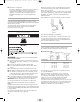
W10135154B EnFrv10.qxd:YB70809-10135134A 4/20/10 2:42 PM Page 15 3. Connect ground wire (green or bare) of power supply cord to external ground conductor screw. Tighten screw. Power supply cord, 4-wire connection: IMPORTANT: A 4-wire connection is required for mobile homes and where local codes do not permit the use of 3-wire connections. D A B F B A C C D E F G E A. 4-wire receptacle (NEMA type 14-30R) B. 4-prong plug C. Ground prong D. Neutral prong E.
W10135154B EnFrv10.qxd:YB70809-10135134A 4/20/10 2:42 PM Page 16 Power supply cord, 3-wire connection: B D E A C G F Use where local codes permit connecting cabinet-ground conductor to neutral wire. 1. Loosen or remove center silver-colored terminal block screw. 2. Connect neutral wire (white or center wire) of power supply cord to the center, silver-colored terminal screw of the terminal block. Tighten screw. 3. Connect the other wires to outer terminal block screws. Tighten screws. A.
W10135154B EnFrv10.qxd:YB70809-10135134A 4/20/10 2:42 PM Page 17 Direct wire cable must match power supply (4-wire or 3-wire) and be: ■ Flexible armored cable or nonmetallic sheathed copper cable (with ground wire), protected with flexible metallic conduit. All current-carrying wires must be insulated. ■ 10-gauge solid copper wire (do not use aluminum). ■ At least 5 ft. (1.52 m) long. 1. Disconnect power. 2. Remove hold-down screw and terminal block cover. Direct Wire Method – U.S. Only D C A.
W10135154B EnFrv10.qxd:YB70809-10135134A 4/20/10 2:42 PM Direct Wire, 4-wire connection: Page 18 3. Connect ground wire (green or bare) of direct wire cable to external ground conductor screw. Tighten screw. IMPORTANT: A 4-wire connection is required for mobile homes and where local codes do not permit the use of 3-wire connections. Direct wire cable must have 5 ft (1.52 m) of extra length so dryer can be moved if needed.
W10135154B EnFrv10.qxd:YB70809-10135134A 4/20/10 2:42 PM Page 19 Direct wire, 3-wire connection: Use where local codes permit connecting cabinet-ground conductor to neutral wire. Direct wire cable must have 5 ft (1.52 m) of extra length so dryer can be moved if needed. Strip 31⁄2" (89 mm) of outer covering from end of cable. Strip insulation back 1" (25 mm). If using 3-wire cable with ground wire, cut bare wire even with outer covering. Shape ends of wires into a hook shape. 1" m) (25 m 1.
W10135154B EnFrv10.qxd:YB70809-10135134A 4/20/10 2:42 PM Page 20 Optional, 3-wire connection: Use for direct wire or power supply cord where local codes do not permit connecting cabinet-ground conductor to neutral wire. 1. Remove center, silver-colored terminal block screw. 2. Remove neutral ground wire from external ground conductor screw. Connect neutral ground wire and the neutral wire (white or center wire) of power supply cord/cable under center, silver-colored terminal block screw. Tighten screw.
W10135154B EnFrv10.qxd:YB70809-10135134A 4/20/10 2:42 PM Page 21 REVERSING THE DOOR SWING Door swing can be changed from a right-side opening to left-side opening, if desired. Place a towel or soft cloth on top of the dryer or work space to prevent scratching the surface. Remove the Door Assembly Reverse Hinge 1. Use a small flat-blade screwdriver to remove 2 plug strips from the inner door. Slide the head of the screwdriver under the plugs, being certain not to scratch the inner door surface.
W10135154B EnFrv10.qxd:YB70809-10135134A 4/20/10 2:42 PM Page 22 Reverse the strike 1. Use a small flat-blade screwdriver to remove plug strip from the dryer door opening. Slide the head of the screwdriver under the plugs, being certain not to scratch the dryer surface. Lift the plastic strip from the dryer slowly to prevent distortion of the plug strip. 2. Remove the strike using a Phillips screwdriver. 3. Insert strike on the opposite side. Reinstall the door 1.
W10135154B EnFrv10.qxd:YB70809-10135134A 4/20/10 2:42 PM Page 23 ELECTRONIC CONTROL SETUP GENERAL USER INFORMATION CONTROL SET-UP PROCEDURES Scrolling “out of order” showing in display, followed by a failure code This condition indicates the dryer is inoperative. IMPORTANT: Read all instructions before operating. The fabric setting buttons along with the digital display are used to set-up the dryer controls. The display can contain 4 numbers and/or letters and a decimal point.
W10135154B EnFrv10.qxd:YB70809-10135134A 4/20/10 2:42 PM Page 24 DISPLAY CODE After the dryer has been installed and plugged in, the display will show ‘0 minutes.’ Once the dryer has been plugged in and the dryer door opened and closed, the display will show the price. In PR models set for free cycles, the display will flash ‘SELECT CYCLE’ and the cycle time. PD Models 1. 0 0 PRICE PR Models SET-UP CODES P The set-up code is indicated by the one or two left hand characters.
W10135154B EnFrv10.qxd:YB70809-10135134A CODE 4/20/10 2:42 PM Page 25 EXPLANATION OPTIONS TO USE IF SPECIAL PRICING IS SELECTED (continued): 7. 0 0 SPECIAL PRICE START HOUR NOTE: Uses military time – 24 hr. clock. 7. 0 0 This is the start hour, 0-23 hours. Select START HOUR by pressing WHITES AND COLORS button. Press PERM. PRESS button once to advance to next code. 8. 0 0 SPECIAL PRICE STOP HOUR NOTE: Uses military time – 24 hr. clock. 8. 0 0 This is the stop hour; 0-23 hours.
W10135154B EnFrv10.qxd:YB70809-10135134A 4/20/10 2:42 PM Page 26 If cycle counter (9 0C) is selected, the following is true: 1 00 Represents the number of cycles in HUNDREDS. 1 02 = 200 2 00 Represents the number of cycles in ONES. 2 25 = 225 TOTAL CYCLES = 225 This is ‘VIEW ONLY’ and cannot be cleared. Press the PERM. PRESS button once to advance to next code. If money counter (1.0C or 1.C0) is selected, the following is true: 3 00 Number of dollars in HUNDREDS. 3 01 = 100.
W10135154B EnFrv10.
W10135154B EnFrv10.qxd:YB70809-10135134A 4/20/10 2:42 PM Page 28 SÉCURITÉ DE LA SÉCHEUSE Votre sécurité et celle des autres est très importante. Nous donnons de nombreux messages de sécurité importants dans ce manuel et sur votre appareil ménager. Assurez-vous de toujours lire tous les messages de sécurité et de vous y conformer. Voici le symbole d’alerte de sécurité. Ce symbole d’alerte de sécurité vous signale les dangers potentiels de décès et de blessures graves à vous et à d’autres.
W10135154B EnFrv10.
W10135154B EnFrv10.qxd:YB70809-10135134A 4/20/10 2:42 PM Page 30 IMPORTANTES INSTRUCTIONS DE SÉCURITÉ AVERTISSEMENT : Pour réduire le risque d'incendie, de choc électrique ou de blessure lors de l'utilisation de la sécheuse, il convient d'observer certaines précautions élémentaires dont les suivantes : I I I I I I I I Lire toutes les instructions avant d'utiliser la sécheuse. Ne pas placer des articles exposés aux huiles de cuisson dans votre sécheuse.
W10135154B EnFrv10.qxd:YB70809-10135134A 4/20/10 2:42 PM Page 31 Exigences d’emplacement Distances de séparation minimales 14"(356 mm) max. 15" (381 mm)* *On doit prévoir un espacement additionnel pour tenir compte éventuellement des moulures du mur, de la porte et du plancher, ou si le circuit d’évacuation comporte un coude. Porte du placard 0" (0 mm) 0" (0 mm) 0" (0 mm) 1" (25 mm) Placard, vue latérale Encastrement, vue avant 3" (76 mm) 48 in2.
W10135154B EnFrv10.qxd:YB70809-10135134A 4/20/10 2:42 PM Page 32 Spécifications électriques - sécheuse à gaz Méthode recommandée de liaison à la terre Après l’installation, la sécheuse doit être électriquement reliée à la terre conformément aux prescriptions des codes et règlements locaux; en l’absence de code local, respecter les prescriptions du code national en vigueur : National Electrical Code, ANSI/NFPA 70 (édition la plus récente), ou Code canadien de l’électricité, CSA C22.
W10135154B EnFrv10.qxd:YB70809-10135134A 4/20/10 2:42 PM Page 33 Spécifications électriques Pour le Canada seulement INSTRUCTIONS DE LIAISON À LA TERRE Pour une sécheuse reliée à la terre et connectée par un cordon : Cette sécheuse doit être reliée à la terre. En cas de mauvais fonctionnement ou de panne, la liaison à la terre réduira le risque de choc électrique en offrant au courant électrique un acheminement d'évacuation de moindre résistance.
W10135154B EnFrv10.qxd:YB70809-10135134A 4/20/10 2:42 PM Page 34 Spécifications de l’alimentation en gaz AVERTISSEMENT Risque d’explosion Utiliser une canalisation neuve d’arrivée de gaz approuvée par la CSA International. Installer un robinet d’arrêt. Bien serrer chaque organe de connexion de la canalisation de gaz. En cas de connexion au gaz propane, demander à une personne qualifiée de s’assurer que la pression de gaz ne dépasse pas 330 mm (13 po) de la colonne d’eau.
W10135154B EnFrv10.qxd:YB70809-10135134A 4/20/10 2:42 PM Page 35 ■ Robinet d’arrêt nécessaire : Conformément aux prescriptions du National Fuel Gas Code, ANSI Z223.1, on doit installer un robinet d’arrêt manuel sur la canalisation d’alimentation, à moins de 6 pi (1,8 m) de la sécheuse. Au Canada, le robinet d’arrêt manuel doit être installé conformément aux prescriptions des codes d’installation B149 – CAN/CGA B149.1 et CAN/CGA B149.2.
W10135154B EnFrv10.qxd:YB70809-10135134A 4/20/10 2:42 PM Page 36 Longueur du circuit d'évacuation La longueur maximale du circuit d’évacuation dépend du type de conduit utilisé, du nombre de coudes et du type de bouche de décharge. La longueur totale du conduit métalllique souple ne doit pas dépasser 73⁄4 pi (2,4 m). La longueur maximale pour le circuit de conduit rigide ou flexible est indiquée dans le tableau ci-après.
W10135154B EnFrv10.qxd:YB70809-10135134A 4/20/10 2:42 PM Page 37 INSTRUCTIONS D’INSTALLATION – SÉCHEUSE À GAZ Raccordement à la canalisation de gaz AVERTISSEMENT 1. Retirer le capuchon rouge de la canalisation de gaz. 2. Raccorder la canalisation de gaz à la sécheuse. Utiliser un composé d’étanchéité compatible avec le gaz propane. Si un conduit métallique flexible est utilisé, vérifier qu’il n’est pas déformé. Si cela est nécessaire à l’entretien, ouvrir le panneau de plinthe.
W10135154B EnFrv10.qxd:YB70809-10135134A 4/20/10 2:42 PM Page 38 INSTRUCTIONS D’INSTALLATION – SÉCHEUSE ÉLECTRIQUE Raccordement du conduit d’évacuation Achever l’installation 1. Une fois la sécheuse à son emplacement final, placer un niveau sur le sommet de la sécheuse, transversalement, puis dans le sens avant arrière. Si la sécheuse n’est pas d’aplomb, ajuster les pieds pour modifier la hauteur et établir un bon aplomb de la sécheuse. 1.
W10135154B EnFrv10.qxd:YB70809-10135134A 4/20/10 2:42 PM Page 39 Inversion du sens d’ouverture de la porte Le sens d’ouverture de la porte peut être changé du côté droit au côté gauche, si désiré. Placer une serviette ou un linge doux sur le dessus de la sécheuse ou du plan de travail pour empêcher rayer la surface. 4. Soulever la partie interne de la porte hors de la partie externe. 5. Faire pivoter la partie externe de 180°. Ôter la porte 1.
W10135154B EnFrv10.qxd:YB70809-10135134A 4/20/10 2:42 PM Page 40 2. Ôter les 4 vis qui fixent la charnière de la porte interne et déplacer la charnière de l’autre côté. Réinstaller les 4 vis. Inversion de la gâche 1. Utiliser un petit tournevis à lame plate pour enlever la tringle des pitons d’obturation des trous dans l’ouverture de la porte de la sécheuse. Faire glisser la tête du tournevis sous les tringles, en veillant à ne pas érafler la surface de la sécheuse.
W10135154B EnFrv10.qxd:YB70809-10135134A 4/20/10 2:42 PM Page 41 INSTRUCTIONS D’ENTRETIEN Instructions d’entretien : Nettoyer le filtre à charpie après chaque utilisation. ■ Comment enlever la charpie accumulée : • De l’intérieur de la sécheuse : Il faut retirer la charpie tous les 2 ans ou plus souvent, selon l’utilisation de la sécheuse. Le nettoyage doit être effectué par une personne qualifiée.
W10135154B EnFrv10.qxd:YB70809-10135134A 4/20/10 2:42 PM Page 42 RÉGLAGE DE COMMANDE ÉLECTRONIQUE INFORMATION GÉNÉRALE POUR L’UTILISATEUR Défilement de “out of order” (hors service) sur l’afficheur, suivi par un code de défaillance Cette situation indique que la sécheuse n’est pas opérationnelle. Affichage de ‘0 Minutes’ Ceci indique qu’il n’est pas possible de faire fonctionner la sécheuse.
W10135154B EnFrv10.qxd:YB70809-10135134A 4/20/10 2:42 PM Page 43 Modèles PR configurés en tant que PN : Les procédures de paramétrage peuvent être entrées en utilisant le Code d’accès pour entretien. On peut entrer ce code pour accéder au mode d’entretien sans retirer la console sur les sécheuses juste enlevées du carton ou sans configuration de prix.
W10135154B EnFrv10.qxd:YB70809-10135134A CODE 4/20/10 2:42 PM Page 44 EXPLICATION 1. 0 0 OPTION COMPTEUR DE MONNAIE Cette option peut être Sélectionnée (‘ON’) ou Pas sélectionnée (‘OFF’). Pas sélectionnée (‘OFF’). 1. 0 0 Option sélectionnée (‘ON’). 1. 0 C Appuyer 3 fois consécutives sur la touche DELICATES pour sélectionner ‘ON’ (active); appuyer 3 fois sur la touche pour désélectionner l’option (Pas sélectionnée [‘OFF’]). Le compteur passe de ‘OFF’ (inactive) à ‘ON’ (active).
W10135154B EnFrv10.qxd:YB70809-10135134A CODE 4/20/10 2:42 PM Page 45 EXPLICATION CODE 8. C E 8.00 OPTION GLISSIÈRE À PIÈCES Cette option peut être Sélectionnée (‘ON’) ou Pas sélectionnée (‘OFF’). Le boîtier du compteur doit être replacé pour le montage de la glissière à pièces. Pas sélectionnée (‘OFF’). 8.00 Option sélectionnée (‘ON’). 8. CS NOTE : Cette option devrait être réglée à ‘00’ à moins que le boîtier du compteur ait été changé pour un dispositif de glissière à pièces.
W10135154B EnFrv10.
W10135154B EnFrv10.
W10135154B EnFrv10.qxd:YB70809-10135134A W10135154B © 2010 All rights reserved. Tous droits réservés. 4/20/10 2:42 PM Page 48 ® Registered Trademark/TM Trademark of Maytag Corporation or its related companies. Used under license by Maytag Limited in Canada. ® Marque déposée/TM Marque de commerce de Maytag Corporation ou ses compagnies affiliées. Emploi sous license par Maytag Limited au Canada. 04/2010 Printed in U.S.A. Imprimé aux É.-U.