Service This manual is to be used by qualified appliance technicians only. Maytag does not assume any responsibility for property damage or personal injury for improper service procedures done by an unqualified person.
Important Information Pride and workmanship go into every product to provide our customers with quality products. It is possible, however, that during its lifetime a product may require service. Products should be serviced only by a qualified service technician who is familiar with the safety procedures required in the repair and who is equipped with the proper tools, parts, testing instruments and the appropriate service information.
Table of Contents Important Information ................................................... 2 Important Safety Information All Appliances .......................................................... 4 Surface Cooking Units ............................................. 4 Ovens ....................................................................... 5 Self-Cleaning Ovens ................................................ 5 Glass/Ceramic Cooking Surfaces ............................ 5 Ventilation Hoods ............
Important Safety Information ! ALL APPLIANCES WARNING To reduce the risk of the appliance tipping, it must be secured by a properly installed anti-tip bracket(s). To make sure bracket has been installed properly, remove the storage drawer and look under the range with a flashlight. Bracket(s) must be engaged in the rear corner of the range. • ALL RANGES CAN TIP • INJURY TO PERSONS COULD RESULT 4. Wear Appropriate Apparel—Loose fitting or hanging garments should never be worn while using appliance. 5.
Important Safety Information OVENS In Case of Fire 1. Use Care When Opening Door—Let hot air or steam escape before removing or replacing food. Fires can occur as a result of over cooking or excessive grease. Though a fire is unlikely, if one occurs, proceed as follows: 2. Do Not Heat Unopened Food Containers—Buildup of pressure may cause container to burst and result in injury. 3. Keep Oven Vent Ducts Unobstructed. 4.
Important Safety Information Product Safety Devices Safety devices and features have been engineered into the product to protect consumer and servicer. Safety devices must never be removed, bypassed, or altered in such a manner as to defeat the purpose for which they were intended. Grounded Oven Frame Ground prong on power cord is connected to the frame, usually a green lead fastened by a screw. Any part or component capable of conducting an electric current is grounded by its mounting.
General Information This manual provides basic instructions and suggestions for handling, installing and servicing electric ranges. The directions, information, and warnings in this manual are developed from experience and careful testing of the product. If the unit is installed according to this manual, it will operate properly and will require minimal servicing. A unit in proper operating order ensures the consumer all the benefits provided by clean, modern electric cooking.
General Information Specifications Refer to individual Technical Sheet for specification information. Placement of the Oven This freestanding range must be placed in the kitchen or comparable room. All safety guidelines must be followed (see Chapter 2) and free air flow around the range is essential. Do Not Block Air Vents All air vents must be kept clear during cooking. If air vents are covered during operation, the oven may overheat.
Range Description Range Description Cooking Surface Downdraft Vent Infinite Switches Electronic Controls Oven Cavity: Broil Element Bake Element Convection Fan Baking Racks Temperature Probe Access Panel: Model Number Rating Label ©2005 Maytag Services 16025927 9
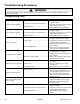
Troubleshooting Procedures ! WARNING To avoid risk of electrical shock, personal injury, or death, disconnect power to oven before servicing, unless testing requires power. Troubleshooting Chart Problem No bake element operation No broil element operation Oven not operating Clock and timer not working Oven light does not operate Oven door will not unlock Oven smokes/odor first few times of usage Surface element doesn’t heat 10 Possible Cause Correction Open bake element ........................
Troubleshooting Procedures ! WARNING To avoid risk of electrical shock, personal injury, or death, disconnect power to oven before servicing, unless testing requires power. Problem Self-clean cycle not working Frequent cycling of surface element or warming zone Possible Cause Correction Programming error ..................................... • Turn off circuit breaker for five minutes and try oven again. Door lock ....................................................
Troubleshooting Procedures ! WARNING To avoid risk of electrical shock, personal injury, or death, disconnect power to oven before servicing, unless testing requires power.
Component Testing Procedures ! WARNING To avoid risk of electrical shock, personal injury or death; disconnect power to oven before servicing, unless testing requires power. Component Testing Procedures Illustration Primary Secondary Primary Secondary Component Oven light housing All models Test Procedure Results Disconnect connector and test Verify bulb is plugged in properly. resistance of terminals ........................... Indicates continuity with bulb installed.
Testing Procedures ! WARNING To avoid risk of electrical shock, personal injury or death; disconnect power to oven before servicing, unless testing requires power. Illustration TOP Component Temperature sensor All models Test Procedure Results Measure resistance .............................. Approx. 1100 Ω at room temperature 75° F (23.8° C). Infinite switch All models Remove wiring from H1 and H2. Approx.
Testing Procedures ! WARNING To avoid risk of electrical shock, personal injury or death; disconnect power to oven before servicing, unless testing requires power. Oven Control Testing Procedures Changing factory set default options: 1. 2. 3. 4.
Testing Procedures ! WARNING To avoid risk of electrical shock, personal injury or death; disconnect power to oven before servicing, unless testing requires power.
Testing Procedures ! WARNING To avoid risk of electrical shock, personal injury or death; disconnect power to oven before servicing, unless testing requires power.
Testing Procedures ! WARNING To avoid risk of electrical shock, personal injury or death; disconnect power to oven before servicing, unless testing requires power. "Quick Test" Mode for Electronic Oven Control (EOC) II Follow the procedure below to perform the EOC II quick test. Instructions must be entered within 16 seconds of each other (via the touch pad) or the EOC will exit the test mode. 1. Press and hold the Cancel and Broil pads for 3 seconds at power-up, or within 5 minutes of power-up. 2.
Testing Procedures ! WARNING To avoid risk of electrical shock, personal injury or death; disconnect power to oven before servicing, unless testing requires power. Description of Fault Codes Each Fault Code consists of an "F" followed by a number, dash and a number or letter. The following table describes each Fault Code and the component to troubleshoot. To view the most recent fault code: 1. Press and hold the Cancel and Broil pads for 3 seconds at power-up, or within 5 minutes of power-up. 2.
Disassembly Procedures To avoid risk of electrical shock, personal injury or death; disconnect power to unit before servicing. Removing and Replacing Range 1. Remove power from unit. 2. Disconnect downdraft blower motor and remove flex ducting to the blower and range (select models). NOTE: To avoid countertop damage, do not move range forward until range has been raised enough to clear all cabinetry. 8. Remove screws securing element mounting brackets to main top assembly (select models). 9.
Disassembly Procedures To avoid risk of electrical shock, personal injury or death; disconnect power to unit before servicing. Bottom Access Panel Transformer 1. Grasp top of bottom access panel and gently pull down and out. 2. Reverse procedure to reinstall bottom access panel. 1. 2. 3. 4. 5. Indicator Lights 1. Remove control panel, see "Control Panel" procedure for removal. 2. Label and disconnect wires from indicator light. 3.
Disassembly Procedures To avoid risk of electrical shock, personal injury or death; disconnect power to unit before servicing. Oven Sensor 1. Remove power from unit. 2. Open oven door and remove screws securing sensor to oven cavity. NOTE: Reposition fiberglass insulation around light socket to eliminate the possibility of any heat related problems. Bulb NOTE: Gently pull wiring through cavity wall. 3. Disconnect oven sensor at the connector terminal and remove. 4. Reverse procedure to reinstall sensor.
Disassembly Procedures To avoid risk of electrical shock, personal injury or death; disconnect power to unit before servicing. Door Latch Oven Door Hinge 1. Remove power from unit. 2. Remove unit from installation position, see “Removing and Replacing Range” procedure. 3. Remove oven door, see "Oven Door Removal" procedure. 4. Remove front side trim, see "Front Side Trim" procedure. 5. Remove the top and bottom screws securing hinge receiver to the front frame. 6. Remove hinge receiver from oven chassis.
Disassembly Procedures To avoid risk of electrical shock, personal injury or death; disconnect power to unit before servicing. NOTE: Proceed with the following steps for inner door disassembly. 10.Remove screws securing lower door glass retainer to door baffle and remove. 11 Slide inner door glass downward to release from upper door glass retainers and remove. 12.Remove screws securing door baffle to door lining and remove. 13.Remove insulation from oven door. 14.
Appendix A ©2005 Maytag Services 16025927 A–1
Installation Instructions (Models JES8750AA*, JES8850A**) IMPORTANT PLEASE KEEP FOR THE USE OF THE LOCAL ELECTRICAL INSPECTOR. FIGURE 1 NOTE: Figure may not be representative of actual unit. The 30 inches (76.2 cm) minimum clearance between the top of the cooking surface and the bottom of an unprotected wood or metal cabinet can be reduced to 24 inches (61 cm) minimum when bottom of wood or metal cabinet is protected by not less than 1/4-inch (6.
Installation Instructions (Models JES8750AA*, JES8850A**) FIGURE 2 FIGURE 3 Notes: 1. Provide for either a 3-wire or 4-wire 120/208, 120/240 volt outlet per applicable cord in shaded area shown. Refer to installation instructions for proper positioning of outlet. 2. Dimension K (figure 4, page 4) is from the wall to the side edge of the oven door. It does not include the curvature of the glass or the depth of the handle. 3. Dimension L (figure 4, page 4) is with the leveler legs adjusted all the way in.
Installation Instructions (Models JES8750AA*, JES8850A**) MOBILE HOMES LOCATING THE RANGE The installation of a range designed for mobile home installation must conform with the Manufactured Home Construction and Safety Standard, Title 24 CFR, Part 3280 (formerly the Federal Standard for Mobile Home Construction and Safety, Title 24 HUD, Part 280) or, when such standard is not applicable, the Standard for Manufactured Home Installations 1982 (Manufactured Home Sites, Communities and Set-Ups), ANSI A225.
Installation Instructions (Models JES8750AA*, JES8850A**) STEP 2 - Anti-Tip Bracket Installation Options A. Wood Construction: 1. Floor: Locate the center of the two holes identified in figure 5 as “HOLES FOR FLOOR.” Drill a 1/8 (3 mm) pilot hole in the center of each hole (a nail or awl may be used if a drill is not available). Secure the ANTI-TIP bracket to the floor with the two screws provided. Proceed to STEP 3. 2. Wall: Locate the center of the two holes identified in figure 5 as “HOLES FOR WALL.
Installation Instructions (Models JES8750AA*, JES8850A**) CONNECTING THE RANGE ELECTRIC SUPPLY RANGE CONNECTIONS The range must be installed in accordance with Local and National Electric Code (NEC) ANSI/NFPA No. 70-latest edition. See rating plate for total connected KW rating. Some models are shipped direct from the factory with service cords (pigtails) attached. There are no range connections necessary on these models. Just plug into the range outlet.
Installation Instructions (Models JES8750AA*, JES8850A**) 3-WIRE SERVICE CORD OR CONDUIT INSTALLATION 4-WIRE SERVICE CORD OR CONDUIT INSTALLATION 1. Insure that the copper ground strap IS CONNECTED between the middle post of the main terminal connection block and the range chassis. (MOBILE HOMES OR AS REQUIRED BY CODES) 1. The copper ground strap connected between the neutral (middle) post of the main terminal block and the chassisMUST be cut off as shown in figure 9.
Installation Instructions (Models JES9750A**, JES9800A**, JES9860A**) IMPORTANT PLEASE KEEP FOR THE USE OF THE LOCAL ELECTRICAL INSPECTOR. FIGURE 1 NOTE: Figure may not be representative of actual unit. The 30 inches (76.2 cm) minimum clearance between the top of the cooking surface and the bottom of an unprotected wood or metal cabinet can be reduced to 24 inches (61 cm) minimum when bottom of wood or metal cabinet is protected by not less than 1/4-inch (6.
Installation Instructions (Models JES9750A**, JES9800A**, JES9860A**) FIGURE 2 FIGURE 3 Notes: 1. Provide for either a 3-wire or 4-wire 120/208, 120/240 volt outlet per applicable cord in shaded area shown. Refer to installation instructions for proper positioning of outlet. 2. Dimension K (figure 4, page 4) is from the wall to the side edge of the oven door. It does not include the curvature of the glass or the depth of the handle. 3.
Installation Instructions (Models JES9750A**, JES9800A**, JES9860A**) MOBILE HOMES LOCATING THE RANGE The installation of a range designed for mobile home installation must conform with the Manufactured Home Construction and Safety Standard, Title 24 CFR, Part 3280 (formerly the Federal Standard for Mobile Home Construction and Safety, Title 24 HUD, Part 280) or, when such standard is not applicable, the Standard for Manufactured Home Installations 1982 (Manufactured Home Sites, Communities and Set-Ups)
Installation Instructions (Models JES9750A**, JES9800A**, JES9860A**) STEP 2 - Anti-Tip Bracket Installation Options A. Wood Construction: 1. Floor: Locate the center of the two holes identified in figure 5 as “HOLES FOR FLOOR.” Drill a 1/8 (3 mm) pilot hole in the center of each hole (a nail or awl may be used if a drill is not available). Secure the ANTI-TIP bracket to the floor with the two screws provided. Proceed to STEP 3. 2.
Installation Instructions (Models JES9750A**, JES9800A**, JES9860A**) CONNECTING THE RANGE ELECTRIC SUPPLY RANGE CONNECTIONS The range must be installed in accordance with Local and National Electric Code (NEC) ANSI/NFPA No. 70-latest edition. See rating plate for total connected KW rating. Some models are shipped direct from the factory with service cords (pigtails) attached. There are no range connections necessary on these models. Just plug into the range outlet.
Installation Instructions (Models JES9750A**, JES9800A**, JES9860A**) 3-WIRE SERVICE CORD OR CONDUIT INSTALLATION 4-WIRE SERVICE CORD OR CONDUIT INSTALLATION 1. Insure that the copper ground strap IS CONNECTED between the middle post of the main terminal connection block and the range chassis. (MOBILE HOMES OR AS REQUIRED BY CODES) 1. The copper ground strap connected between the neutral (middle) post of the main terminal block and the chassisMUST be cut off as shown in figure 9.
Installation Instructions (Models JES9750A**, JES9800A**, JES9860A**) DOWNDRAFT INSTALLATION INSTRUCTIONS S Determine where you will be locating the electrical outlet. It must be in the floor or on the wall within the area shown in figure 2 or 3. S Determine how you will be venting your downdraft blower. You may vent through the rear wall, the floor, or the sides. When locating the downdraft vent opening make sure it will not interfere with your electrical outlet. a. Through the rear wall.
Installation Instructions (Models JES9750A**, JES9800A**, JES9860A**) 3. Make cutout in the cabinet floor of either the right or left side cabinet as shown in figures 14 or 15. 4. Relocate the mounting brackets on the blower housing as shown in figure 17. NOTE: The mounting br ackets shown in figure 16 are as assembled at the factory for floor or rear wall venting. Figure 14 Left Cabinet (Top View) a. Right side venting (figure 17). 1. Remove nuts from studs 1, 2 and 3 on the motor side. 2.
Installation Instructions (Models JES9750A**, JES9800A**, JES9860A**) 8. Install the 6 (15.24 cm) elbow of the blower housing and secure with duct tape. The open end of the elbow should be pointed to the left. Attach the 6 (15.24 cm) flex duct (provided with the range) to the elbow and to the range. Note: For right side venting, the 6 (15.24 cm) diameter flex duct may be cut in half and used in order to make assembly easier. INSTALLING THE BLOWER NOTE: Install the blower prior to installing the range.
Appendix B ©2005 Maytag Services 16025927 B–1
Use Information (Models JES8750AA*, JES8850A**) OvENCOOKING Keep Warm Clock _y o_ Bread Timer 2 Oven Light Theelectroniccontrolisdesigned foreaseinprogramming. Thedisplay windowonthecontrolshowstimeofday,timerandovenfunctions. ControlpanelshownincludesConvectandothermodelspecificfeatures.(Stylingmayvarydepending onmodel.) CAUTION: , Besureallpackingmaterialisremovedfromovenbeforeturningon. •PreparedFoodWarning:Follow foodmanufacturer's instructions.
Use Information (Models JES8750AA*, JES8850A**) ]O EN COOKING, coNJ 5.Attheendofthesettime,"END"willbe BAKE PAD CONVECT BAKE PAD/ Useforbakingandroasting. CONVECT ROAST PAD ( SE LE CT MODELS) displayedandtwo chimeswill sound followedbytwochimesevery30secondsforuptofiveminutes.Pressthe correspondingTimer padtocancelthechimes. I.PressBakepad. 2.Pressagainfor330oForpresstheAuto S etpad.
Use Information (Models JES8750AA*, JES8850A**) BROIL PAD Usefortopbrowningorbroiling.Forbest results,usethebroilerpanprovidedwith yourrange, I. PresstheBroilpad. 2, PresstheAuto Setpadforhi broil, pressagainfor Iobroil,or pressthe appropriatenumberpadstosetdesired broiltemperaturebetween300° and 550°F. 3. Foroptimalbroiling,preheatthreeto fourminutesoruntilthebroilelement isred. 4.Attheendofcooktime,theovenwill shutoffautomatically, "End"andCOOK TIMEwillbedisplayed andthreechimes willsound. 5.
Use Information (Models JES8750AA*, JES8850A**) OVEN KEEP WARM COOKING rCONT. PAD (SELECT BR EAD PROOFING QuickProofingprovides fasterresultsthan countertop orstandard proofing,without harmingtheyeast. PAD MODELS) Forsafelykeepi ngfoodsw armorforwarmingbreadsandplates, (SELECT MODELS) Forproofingorallowin gyeastbreadproductstorisepriortobaking.Therearetwo I.PressKeepWarm proofingmethodsavailable-STANDARD 2.PresstheAuto Set padforStandard andQUICK. Proof,pressagainforQuickProof. pad. 2.
Use Information (Models JES9750A**, JES9860A**) O VEN COOKING C ONTROL OPTIONS CONTROL P AD O PERATION B–6 T IMER P ADS S ETTING CONTROL F UNCTIONS C LOCK P AD 16025927 ©2005 Maytag Services
Use Information (Models JES9750A**, JES9860A**) B AKE P AD CONVECT B AKE P AD / CONVECT R OAST P AD (SELECT MODELS ) C ANCEL P AD A UTO S ET P AD ©2005 Maytag Services NOTES: 16025927 B–7
Use Information (Models JES9750A**, JES9860A**) O VEN COOKING , CONT .
Use Information (Models JES9750A**, JES9860A**) K EEP W ARM P AD (SELECT ) MODELS B READ P ROOFING P AD (SELECT MODELS ) NOTES: P ROBE P AD (SELECT MODELS ) ©2005 Maytag Services 16025927 B–9
Use Information (Models JES9750A**, JES9860A**) O VEN COOKING D RYING P AD B – 10 , CONT .
Use Information (Model JES9800A**) OVEN COOKING J-ig[It Drying Timer 1 Bread Timer 2 ct ............................ f4o_Tir_Bee_ TPmt; C/_ La,,guage Det_ult Set,, Theelectroniccontrolisdesignedforeaseinprogramming.Thedisplaywindowonthecontrolshowstimeofday,timerandovenfunctions. CAUTION: " Besure all packingmaterial isremovedfromovenbeforeturningon. • Prep ared Food W arnin g: Follow foodmanufacturer'sinstructions.
Use Information (Model JES9800A**) 5.Attheendofthesettime,"END"willbe BAKE PAD 5.Whencookingiscomplete,pressCa1 displayedandtwo chimeswill sound Useforbakingandroasting, followedbyonechimeevery30seconds I.PressBakepad. foruptofiveminutes.PressthecorrespondingTimer padtocancelthe chimes. NOT E: TheTimerreminderchimesat theendofasettimemaybechanged, SeeControl Options(End-of-Ti mer page13. Si gnal), ToCanc elaSetTime: Pressandholdthecorresponding Ti mer padforseveralseconds.
Use Information (Model JES9800A**) OVEN COOKING, CONT. BROIL PAD 4.Attheendofcooktime,theovenwil{ Usefortopbrowningorbroiling.Forbest results,usethebroilerpanprovidedwith yourrange, 5.PressCancelpad.Removefoodfrom oven. Iftheprogramisnotcanceled, I. PresstheBroilpad. 2. PresstheAuto Set padforhi broil, pressagainfor Iobroil,or pressthe appropriatenumberpadstosetdesired broiltemperaturebetween300° and 550°F. 3. Foroptimalbroiling,preheatthreeto fourminutesoruntilthebroilelement isred. 4.
Care and Cleaning C LEANING P ROCEDURES CLOCK AND C ONTROL P AD A REA D OOR H ANDLE – P LASTIC F INISHES CONTROL P ANEL A CCESS P ANEL G LASS W INDOW & D OOR – CONTROL K NOBS PRONGS PRONGS GREASE CUP O VEN I NTERIORS NAMEL O VEN R ACKS B ROILER P AN B – 14 AND I NSERT 16025927 ©2005 Maytag Services
Care and Cleaning C ARE & C LEANING , CONT .